-
2-
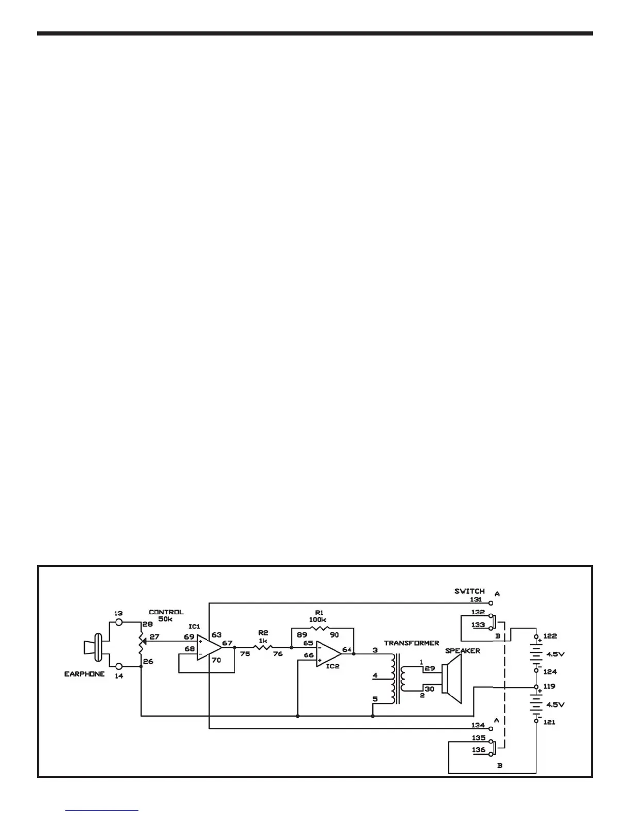
This is another two-power source microphone
amplifier, but this one is an invertin
amplifier. Yo
w
use t
e earp
one as a m
crop
one aga
n
Slide the switch to
osition B and construct th
circuit.
nce you finish the wirin
, slide the switch t
position A to turn the power on, ad
ust the control
clockwise, and s
eak into the
micro
hone” – th
earphone. This project works just like the precedin
.
IC 2 is an inverting amplifier and IC 1 is used as
buffer between the ear
hone and IC2, and has
gain of 1. I
2 is an inverting amplifier, with the inpu
applied throu
h its ne
ative (–) terminal, not the
positive (+) one as in our last project. IC2’s gain is
about 100, as determined by:
R1/R2 = 100k/1k=100.
I
you increase R1 or decrease R2, the
ain become
larger.
ee what occurs to the gain when you alte
the value of R2 to 470.
otes:
EXPERIMENT #7
: INVERTIN
D
AL
PPLY
P AM
Wiring
equence
-2
2-
-
-
27-6
-1
-
-7
-
7-7
7
-1
21-1
22-1
24-119-26-66-5-14-EARPHON
2
-1
-EARPH
NE
chemati