-
-
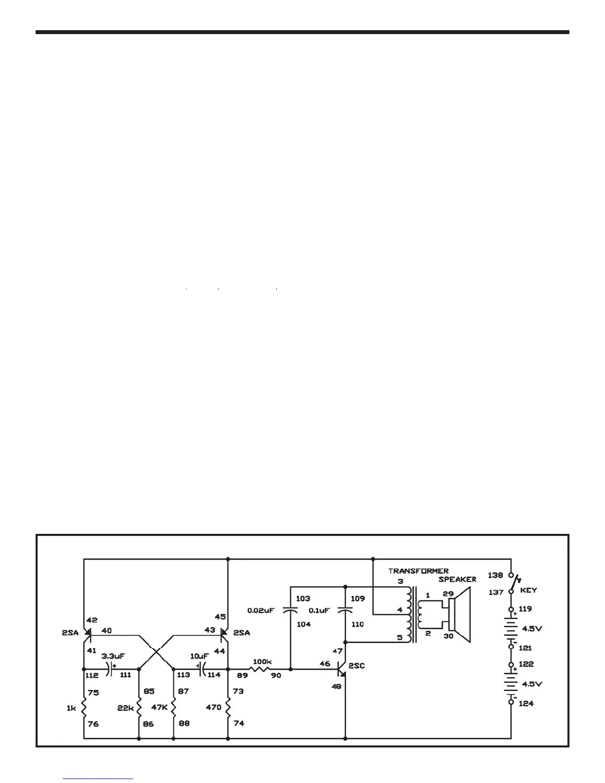
Now you will let one oscillator control another t
create an alarm. Here we have a multivibrator-typ
osc
ator contro
ng a pu
se osc
ator.
e pu
s
oscillator produces frequency in the audible rang
(the ran
e that our ears can hear, about 20 to 20k
Hertz
. The multivibrator circuit on the left side of th
schematic should look familiar. The multivibrato
comman
s t
e pu
se osc
ator
y a
ow
ng current t
low to the transistor base.
Build the experiment and press the key to hear th
alarm sound comin
rom the speaker. You hear th
alarm resonate turning on and o
as the puls
oscillator turns on and o
This intermittent sounding alarm is more bene
icia
than a continuous tone, because it is more
noticeable. You can experiment with this experimen
by varying the values of the 22k
resistors, and the 0.0
capacitor.
N
t
:
EXPERIMENT #
: P
L
E ALARM
Wiring
equence:
1-29
2-
-1
-1
-
-
5-
-47-110
4
-11
-
7
41-112-7
-
-
5
44-114-7
-
4
-1
4-
7
-
-
-7
-
-
119-137
121-122
Schemati