-11
-
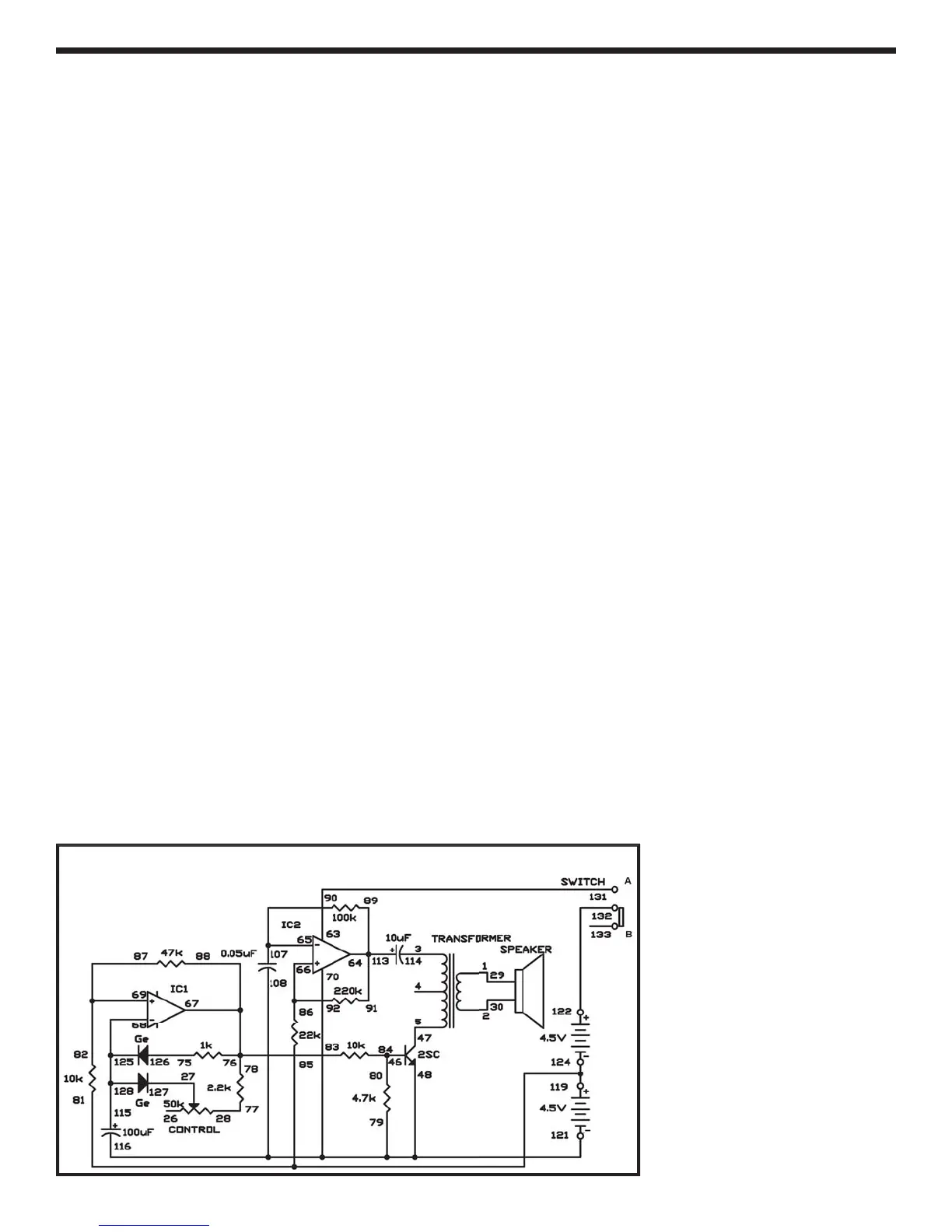
This is the operational amplifier version of th
electronic metronome from Project 3 (“Electroni
etronome”). Slide the switch to position B, an
connect the wires carefully - this project is mor
intricate than most of the others. When you complet
assembling the circuit, set the control to the 1
o’clock position, and slide the switch to position A t
turn on the power. You’ll hear a pip noise
rom th
speaker at
ixed intervals. Now gradually rotate th
control clockwise, and the beats come
aster.
Now observe the schematic. IC 1 and IC 2 are use
as asta
e mu
t
v
rators, as
n our
ast exper
ment
But you’ll notice that I
1 uses diodes to generate
short pulses and the control is used to modi
y th
s
eed of the
ulses. The transistor turns on eac
time a pulse is
enerated, and creates a sound
t
:
EXPERIMENT #
1:
P AMP METR
N
M
Wiring
equence:
1-2
-
-114
5-
7
27-127
-77
6-80-84
-7
-
-
-
-
3-131
9-91-113-6
-
-1
7
6-92-66
8-76-83-88-6
8-115-125-128
-
7-
-12
-
-
-
122-1
2
Schematic