-
-
Here’s a timer you can use for takin
timed tests o
simply for knowin
when an amount of time has
assed. You can
reset this timer for u
to
pproximatel
15 minutes. When the time is up, it
g
ves out a cont
nuous
uzzer soun
unt
you turn
off the power or press the key to reset the circuit.
After you build this experiment, set the control t
osition 2 on the dial and slide the switch to
ositio
to turn on t
e power.
o
a stopwatc
an
start
when you press the key. The timer makes a buzzin
sound in about 30 or more seconds.
et the control to each division on the dial from 2 t
, and note how lon
it takes the timer to produce
sound. Settin
the timer’s calibration - the time tha
passes at each settin
o
the dial - requires a lot o
patience, but it is necessary
or making sure you
timer works accurately. After you set the calibration
you nee
to ma
e a grap
s
ow
ng eac
contro
osition and the time it takes for the buzzer to sound
Then your tester is ready
or use
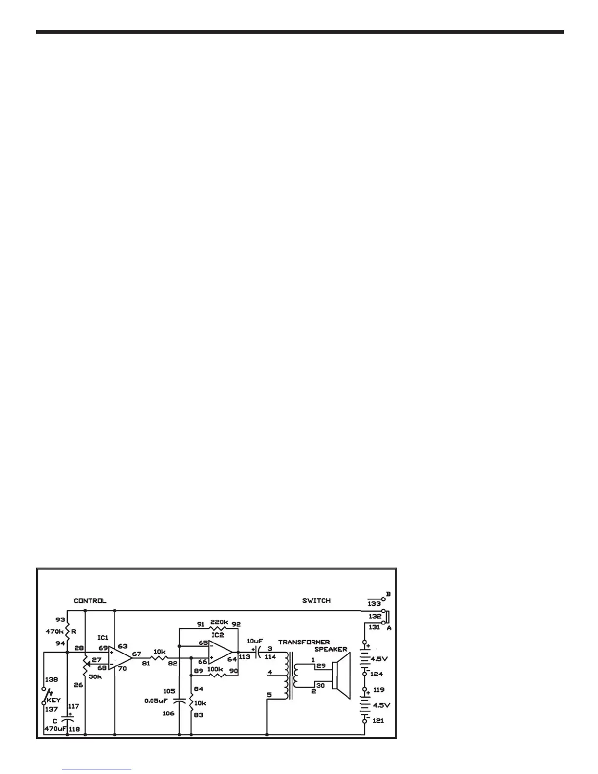
can the schematic. The control changes th
reference voltage of the comparator (I
1). Th
resistor R and the ca
acitor C determine the time
setting. When the voltage applied to the positive
+
terminal of I
1 exceeds the reference volta
e, th
arm soun
s.
The operational ampli
ier has hi
h input impedance
input resistance
, so its current loss is very small
n
you can use
t to ma
e a t
mer w
t
a very
on
settin
. IC 2 works as an astable mulitivibrator that
pro
uces t
e
uzzer soun
.
t
:
EXPERIMENT #1
7: TIME
Wiring Sequence:
-2
-30
-
-
-7
-
-
-
7-
-
93-63-28-132
92-90-64-113
5-105-91
-
2-
4-
7-
94-69-117-138
-
-
Schematic
 Loading...