For this section you will need some basi
understandin
about the operational amplifie
ntegrate
c
rcu
t.
rst, we can use separate powe
sources or we can use one power source for both th
circuit and the I
.
The o
erational am
lifier
often called “o
am
” fo
short
can be operated as a non-invertin
amplifier
an inverting ampli
ier, or a di
erential ampli
ier. A
non-invertin
ampli
ier reproduces an input si
nal as
an output signal without any alteration in polarity. A
invertin
ampli
ier does the reverse: its output ha
the reverse polarity o
its input. The di
erential
ampli
ier has an output that is the contrast between
the stren
ths o
the two input si
nals.
omparing two voltages and telling you which one i
stronger than the other is the job o
a comparator. We
call the controlled volta
e the reference volta
because we use it as a re
erence
or measuring othe
voltages. The voltage that is compared is the inpu
volta
e
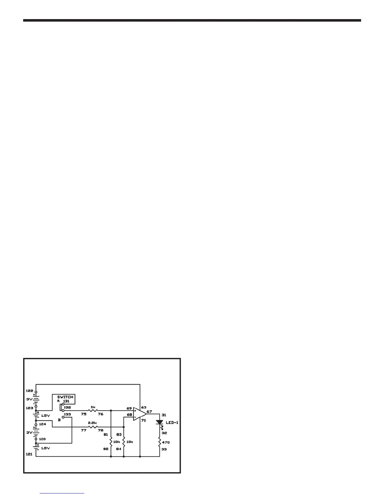
The re
erence volta
e in this experiment is about
3.7V. It is connected to terminal 68 o
one o
the op
amp integrated circuit. Input voltage is connected to
terminal 69 of the same IC. The LED will li
ht if thi
input voltage is higher than the re
erence voltage,
and the LED stays o
i
it is lower. The operationa
amplifier acts as an inverting amplifier for th
re
erence voltage to keep the LED turned o
, or as
non-invertin
amplifier to li
ht the LED
Build the ex
eriment and then set the switch t
position A. This supplies an input o
6V. The LED lights
because the input voltage is higher than the re
erence
volta
e. Now slide the switch to position B. Thi
supplies an input voltage of 1.5V. The comparator I
oes not turn on t
e
,
ecause t
e
nput vo
tag
is now lower than the reference volta
e
t
:
EXPERIMENT #7
:
PERATI
NAL AMPLIFIER
MPARAT
R
Schematic
-
-
Wiring Sequence
1-
-
-
-7
-
3-12
8-83-7
9-81-7
75-13
77-11
-12
-
123-13