Installation and First Start-Up
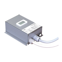
Figure 6: View on the top- and bottom-side of LIMAX33 CP-00 with eSGC
Remark: The top side view of the version without eSGC is slightly deviant:
The eSGC-connector is not fitted and the LED assignment differs depending on the order.
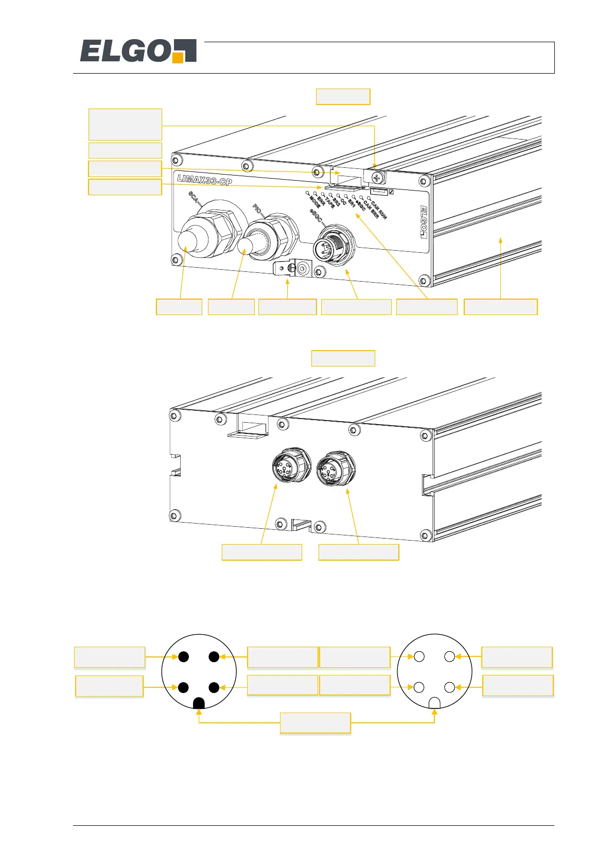
Figure 7: Pin assignment eSGC connector (mechanical data according to IEC 61076-2-101)
LED indicator
Guide rail
Tape guide
Holding plate for
the guide rail
Underlay
Sensor housingEarthing lugSCA cable PIO cable
TOP view
Floor sensor 1 (FS1) Floor sensor 2 (FS2)
BOTTOM view
eSGC connector
1
2
34
SG_GND
SG_OUT
SG_POW
N.C.
2
1
43
N.C.
SG_POWSG_OUT
SG_GND
Coding key
Pin assignment of the male connector
at the top side of LIMAX33 CP
Pin assignment of the counterpart
(female connector) at the cable to the
trip coil of the connected braking
element
 Loading...