TelevisGo Page 11/68
Modules and system devices must be connected using a cable with 0.5 mm
2
conductors. There must be no more than 2km between
TelevisGo and the last module. Comply with relevant applicable legislation when laying data transmission cables.
Use a shielded cable (i.e. Belden cable model 8762 with PVC sleeve, 2 conductors plus braiding, 20 AWG, nominal capacity
between conductors 89pF, nominal capacity of 161pF between conductor and shielding).
Remember to insert a 120Ω, ¼W resistor between the “+” and “-“ terminals of the last device in the network.
To switch the device off, press and hold button (13) for 4 seconds (to prevent any accidental switching off). In the event of
a blackout, the PC and application restart automatically when mains power is returned.
3.4.1 CONFIGURING NETWORK DEVICES
Before scanning the network with TelevisGo, each device in the network must be assigned a unique address by setting parameters
“FAA” and “dEA”.
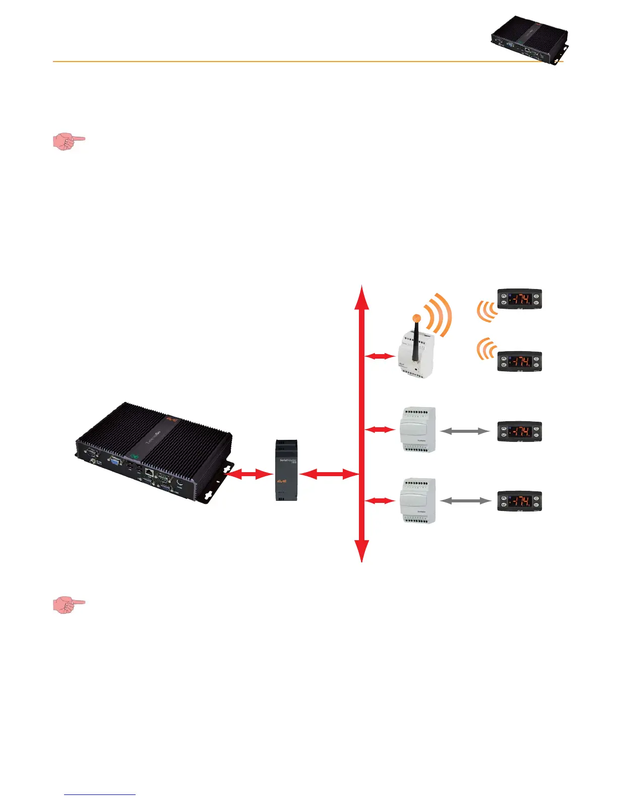
3.4.2 RS-485 CONNECTION
An example of a RS-485 network is provided in the figure below.
Bus Adapter
Bus Adapter
Radio Adapter
RS485
uNet
RS485
It features: 1 SerialAdapter232, 2 BusAdapters, 1 RadioAdapter and 4 ID controllers.
The SerialAdpater232 adapter can only be connected to COM1 or COM2 as it is supplied by them.
Other serial accessories (modems) must be connected to serials COM3 or COM4.