31
SETTING
UP
English
(3) To connect the unit with a composite video input terminal.
Connect a commercially available RCA pin plug video cable to the [VIDEO OUT] terminal
on the rear panel.
(
4) To connect the PC with a USB cable.
Connect the supplied or commercially available USB cable to the [USB] terminal on the rear
panel.
• We recommend using a USB 2.0 compliant USB cable.
•
If you plug into a USB connector with the power on, the PC may not recognize this device.
• Depending on the USB environment used by the PC or peripheral equipment using
the USB 2.0 compliant cable, image transfer may be disrupted.
•
Operation is not guaranteed for all environments.
• Only one image can be output at a time; either [RGB OUT] or [VIDEO OUT]. For more
information on switching the image output, refer to "RGB/Video Switch".
P.15
• To protect the unit and peripheral devices, unplug the power plug and the AC
adapter, and turn off all other devices before connecting the video cable.
•
When plugging in or unplugging the power plug, the AC adapter, or video cable, hold
the plug of the cable.
(
5) To connect the AC adapter.
Connect the DC plug of the supplied AC adapter to the [DC IN 12V] terminal on the rear
panel before inserting the AC adapter in an outlet.
n
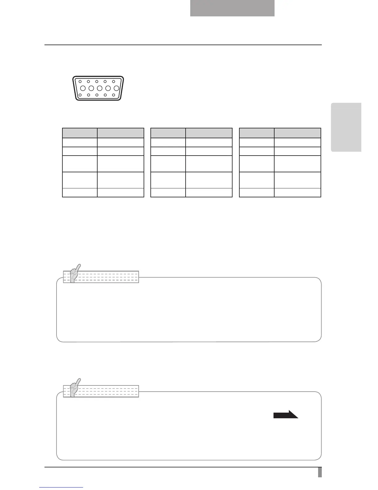
Specifications of the analog RGB input terminal of this product
Signal allocation
10
9 8 7 6
5 4 3 2 1
15 14 13
DSUB 15P shrink terminal (Female)
12 11
Video signal: Analog 0.7V (p-p) with 75Ω terminated
Horizontal synchronized signal: TTL level (Positive/negative polarity)
Vertical synchronized signal: TTL level (Positive/negative polarity)
Pin assignment
Pin No. Name Pin No. Name Pin No. Name
1
Video signal (Red)
6 GND (Red) 11 GND
2
Video signal (Green)
7 GND (Green) 12 N.C
3
Video signal (Blue)
8 GND (Blue) 13
Horizontal syn-
chronized signal
4 N.C 9 N.C 14
Vertical synchro-
nized signal
5 GND 10 GND 15 N.C