28
12
-+U
-
V
M
+I A B C D
PRI
NT
PA
TV
TV
SE
B2
B1
EXT+
EXT-
VLED
X
M
PA
CA
M
S+
S-
+12V
-L
SR
F2
F1
M
T+
-+U
-
V
M
+I A B C D
PRI
NT
T+
-+U
-
V
M
+I A B C D
PRI
NTNT
T+
-+U
-
V
M
+I A B C D
PRI
TC TC
TC
TC
AL AL AL AL
T+
0
28V
1
PRI
2B1B2
AL
IF
NT
SP
V3 MV3 MV4A3 A4V4MA3 MA4
PROGRAM EXPANSION MODULE
V1 MV1 MV2A1 A2V2MA1 MA2
EXT F2 +IF1 B2GND+12V B1
1A
–
+
2A 1B 2B 1C 1D2C 2D
12121 122
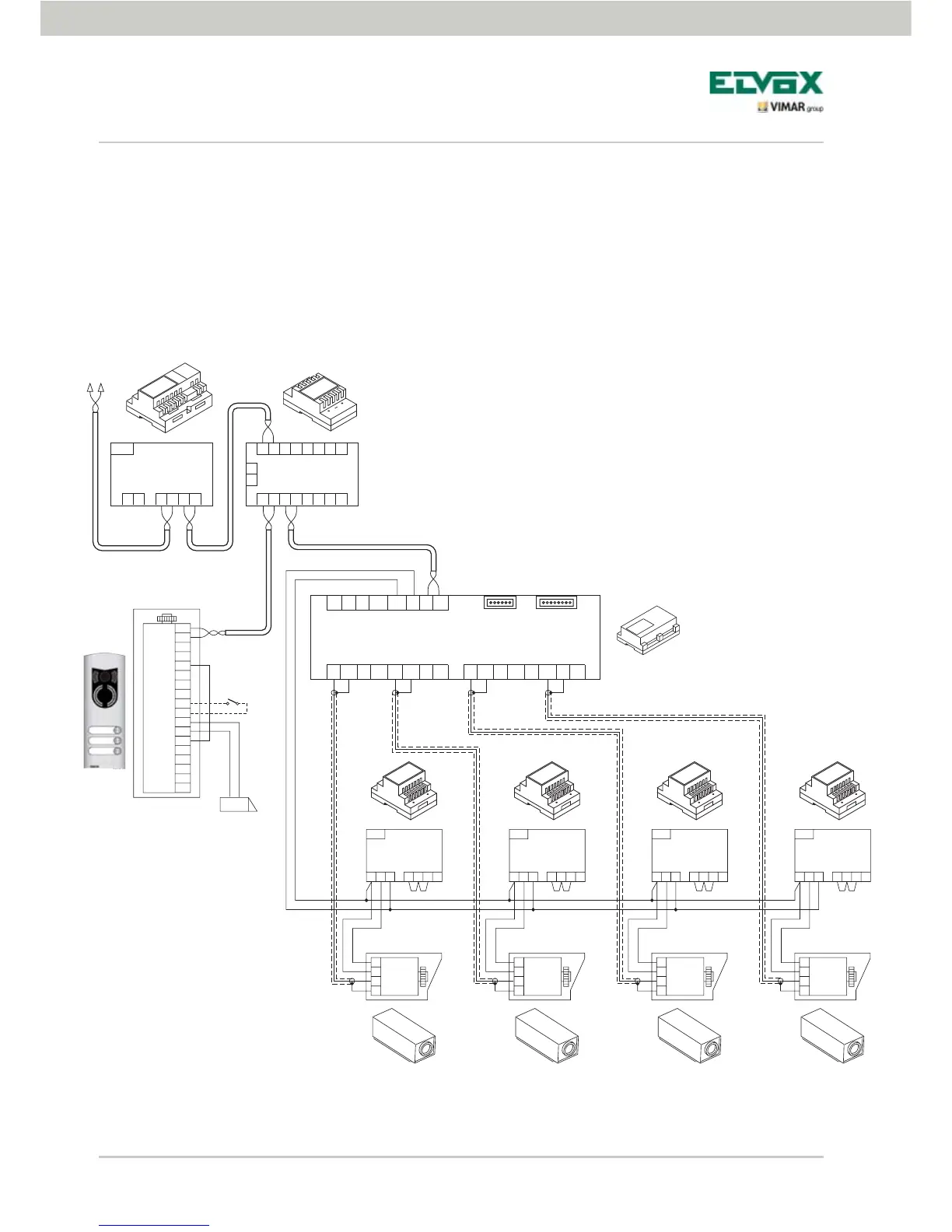
AL - Power supply Art. 6922
IF - Interface for 4 video cameras with audio Art. 69AM
CC - Concentrator Art. 692C
TV - External video panel
NT - Network
PA - Door opening command
SE - Electric lock 12 V DC
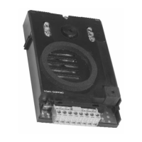
TC - CCTV camera 12 VDC
Figure 26 - Example of
installation of additional
video cameras
Confi guration of the video door entry unit
N.B.: For each video door entry unit it is possible to configure the self-start sequence of the additional video
cameras connected to the audio/video interface 02016; this configuration can be made exclusively with
advanced programming of the audio/video interface by using the PC and the USB interface 692I/U with
the “EVCom” software (see the related technical documentation).