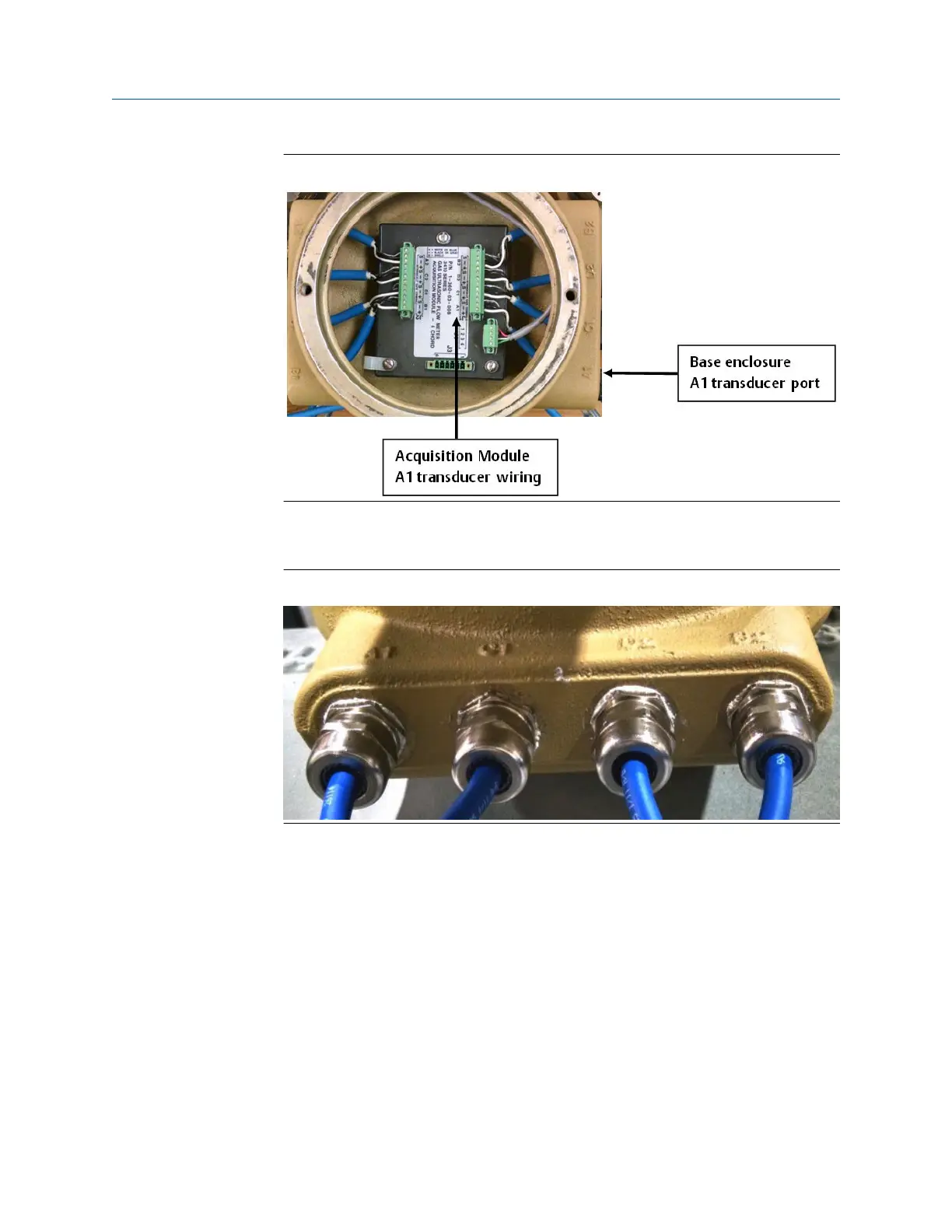
Figure 5-6: Acquisition Module wiring
9. Route the transducer cables through the cable glands with the correct label number
(i.e. A1) which matches the label on the transducer cable.
Figure 5-7: Base enclosure cable glands installation
10. Judge the proper length and cut off the excess.
11. Strip the outer insulation, outer shield, and inner insulation using a utility knife.
Verify that insulation of individual wires was not cut while removing outer layers.
Strip each wire 0.28".
Installing the 3410 Series Electronics Upgrade kit instructions
July 2019 P/N 3-9000-784
32 3410 Series Electronics Upgrade kit instructions

 Loading...


