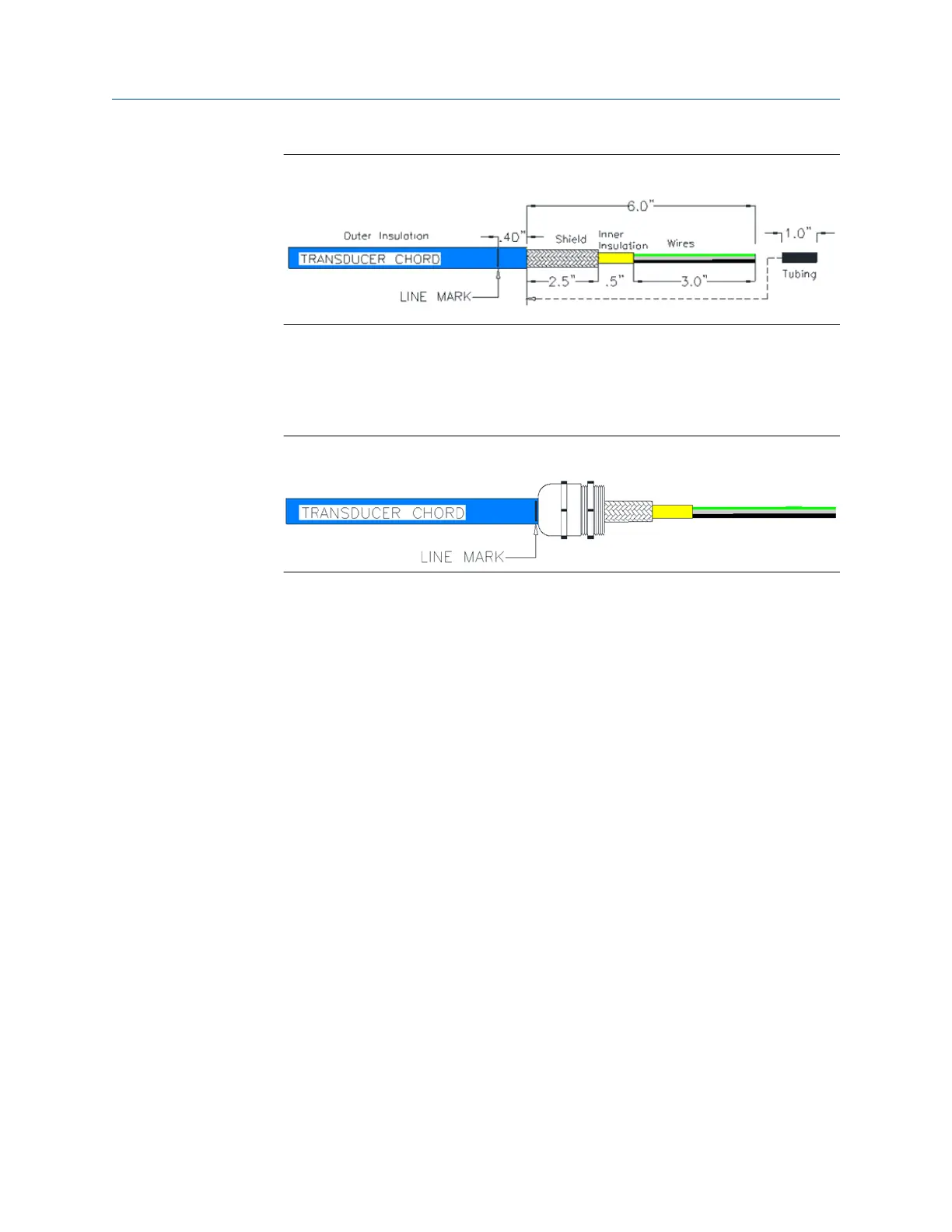
Figure 5-8: Transducer Cable Cut Instructions
12. Insert tubing over wires, inner insulation and under shield approximately 1.5" of
shield should overlap.
13. Insert and secure transducer cables through cable glands verify Line Mark is as
referenced in Figure 5-7.
Figure 5-9: Line mark
14. Using a torque screwdriver set to 34 ±2 oz. in., secure the wires to the terminal
plugs of the Acquisition Module.
15. Verify the cable lengths are still an appropriate length and if necessary, cut the
transducer cables to the correct length with allowance for the wiring terminations
and connector placement.
16. Ensure that the contacts clamp on the bare wires and not on the wire insulation
when the wires are being terminated on the connector.
a) Leave the connector plugged into the Acquisition board while terminating
the individual wires.
b) Tighten the connector screws on the either end of the connector after
terminating all the wires on the applicable connector.
c) Repeat this procedure for the transducer cables on the other side of the
meter.
Upgrade kit instructions Installing the 3410 Series Electronics
P/N 3-9000-784 July 2019
3410 Series Electronics Upgrade kit instructions 33

 Loading...


