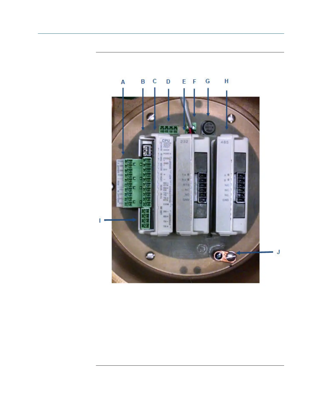
Figure 5-18: Install wiring terminal block connectors to the CPU Module
(shown with Optional I/O Modules)
A. CPU lower terminal block
B. CPU upper terminal block and switches
C. CPU Module
D. 24 VDC loop power
E. Optional RS-232 I/O Module
F. 10.4 - 36 VDC power
G. Fuse
H. Optional RS-485 I/O Module
I. Ethernet terminal block
J. Chassis ground
Installing the 3410 Series Electronics Upgrade kit instructions
July 2019 P/N 3-9000-784
42 3410 Series Electronics Upgrade kit instructions

 Loading...


