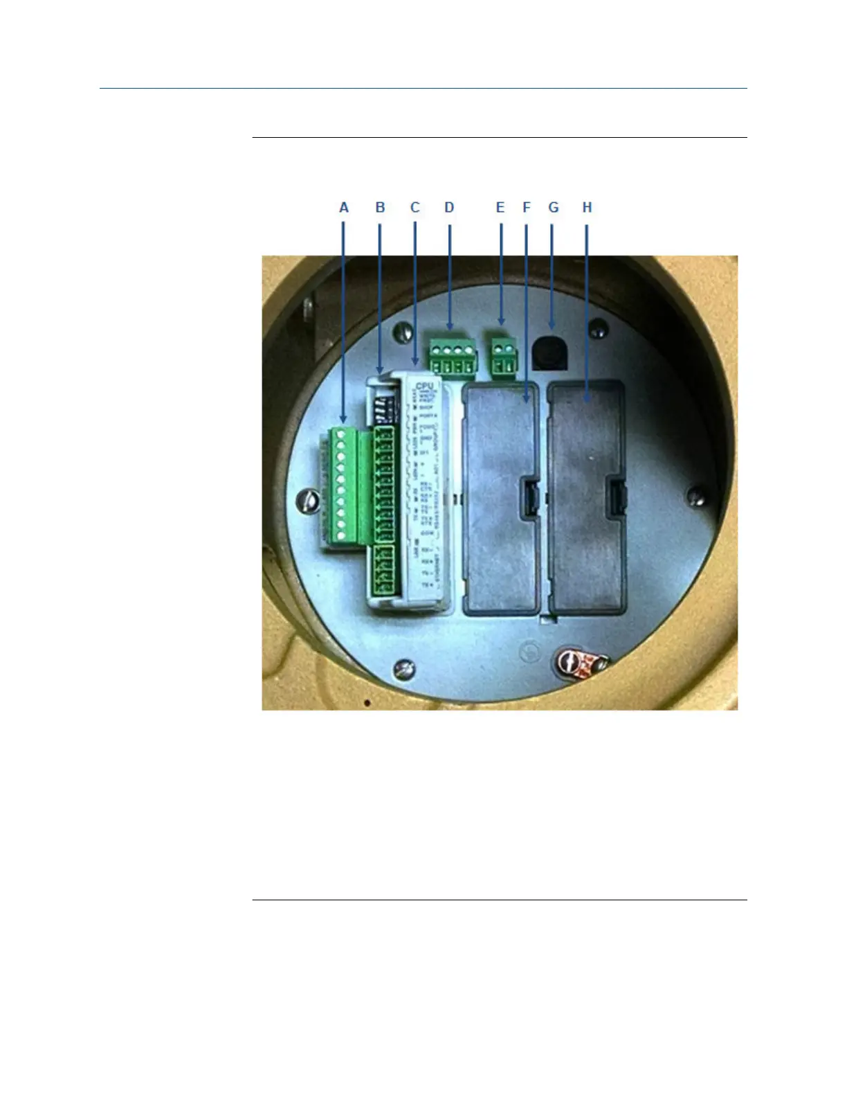
Figure 5-19: Install wiring terminal block connectors to the CPU Module
(shown without Optional I/O Modules)
A. CPU lower terminal block
B. CPU upper terminal block and switches
C. CPU Module
D. 24 VDC loop power
E. 10.4 - 36 VDC power
F. Guide plate blanking cover
G. Fuse
H. Guide plate blanking cover
I. Guide plate blanking cover
All of the terminations in the 3410 Series electronics are removable terminal blocks.
Removing the terminal blocks from the modules before terminating wires to them
makes wiring easier. Appendix C of this document also includes wiring tables and
Upgrade kit instructions Installing the 3410 Series Electronics
P/N 3-9000-784 July 2019
3410 Series Electronics Upgrade kit instructions 43

 Loading...


