8 Unidrive M SI-PROFIBUS User Guide
Issue Number: 3
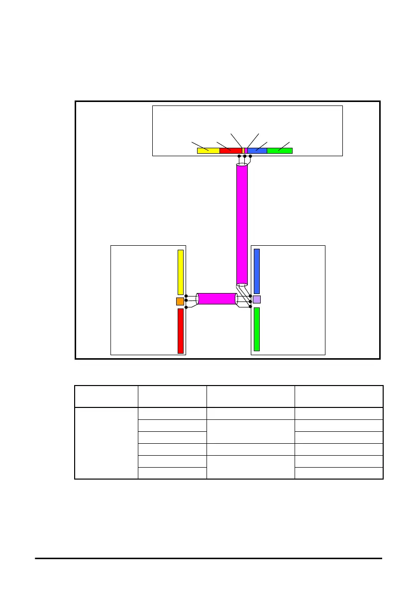
Figure 2-2 shows a typical PROFIBUS-DP network system transferring the same
signals as given in the traditionally wired example. The signals are now transmitted by
converting them into a serial data stream which is received by the master as if they were
connected using traditional wiring. The data stream on PROFIBUS-DP allows up to 64
(32 input and 32 output) independent values to be sent or received by the master, in
addition to a single channel allowing for random access to drive parameters.
Figure 2-2 PROFIBUS-DP cable layout
Table 2.2 Data mappings for SI-PROFIBUS
Table 2.2 details the number of data words used to communicate the signals using the
PROFIBUS-DP network. It can be seen that the resulting reduction in cabling is
significant.
PROFIBUS master
Digital 1A Digital 1B Digital 2A Digital 2B
Analog 1 Analog 2
Analog 1
Analog 2
Digital 2A Digital 2B
Slave Number
2
Slave Number
1
Digital 1ADigital 1B
Number of
network words
Type Source / Destination Description
1
digital Inputs slave 1 to master status signals
digital outputs
master to slave 1
control signals
analog output control signal
digital inputs slave 2 to master status signals
digital outputs
master to slave 2
control signals
analog output control signal