Unidrive M SI-PROFIBUS User Guide 55
Issue Number: 3
Safety
information
Introduction
Mechanical
installation
Electrical
installation
Getting
started
Parameters
GSD
Files
Cyclic data
Non-cyclic
data
Control and
status words
Diagnostics
PROFIdrive
profile (V4)
Advanced
features
Legacy
features
Glossary of
terms
Index
10 Control and status words
10.1 What are control and status words?
The control and status words allow the digital control and monitoring of the drive to be
implemented using a single data word for each function. Each bit in the control word has
a particular function and provides a method of controlling the output functions of the
drive, such as run and direction.
Each bit in the status word provides feedback about the drive’s state of health and
operational condition, such as drive ok, drive at speed, etc.
10.2 Control word
The SI-PROFIBUS control word consists of sixteen control bits some of which are
reserved. See Table 10.1 for the individual bit function descriptions.
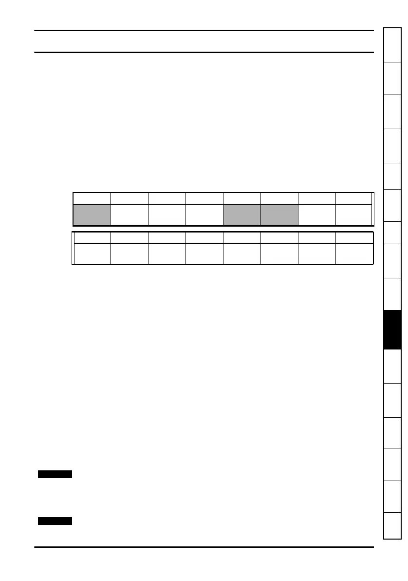
Table 10.1 Control word bit definitions
To enable fieldbus control, the fieldbus enable signal (Pr 06.043) and the AUTO bit (b7)
must both be set to ‘1’. When the AUTO bit is reset to 0 the drive will revert to terminal
control.
For safety reasons, the external HARDWARE ENABLE signal must be present before
the fieldbus control word can be used to start the drive. This terminal is normally
controlled by an external “Emergency Stop” circuit to ensure that the drive is disabled in
an emergency situation.
The control word REMOTE bit directly controls the drive parameter Pr 01.042, the
function of which is to select the digital speed reference as the source of the drive’s
speed reference. When the REMOTE bit is reset to 0 the drive will revert to using the
external analog speed reference.
The actual digital speed reference selected when REMOTE is set to 1 will be Pr 01.021,
which is also the default mapping for the fieldbus speed reference. However Pr 01.015
can be used to change which of the digital references is selected. For further details on
the drive digital speed reference, please refer to the appropriate drive user guide.
Table 10.2 lists in detail the function of each control word bit. For further in-depth details
about drive control words and sequencing bits please refer to the appropriate drive
documentation.
b15 b14 b13 b12 b11 b10 b9 b8
KEYPAD
WDOG
RESET TRIP
JOG
REV
REMOTE
b7 b6 b5 b4 b3 b2 b1 b0
AUTO
NOT
STOP
RUN
FWD
REV
RUN
REV
JOG
FWD
RUN
FWD
ENABLE
When a trip occurs, the drive control word MUST be set to a safe, disabled state. This
ensures that the drive does not re-start unexpectedly when it is reset. This can be
achieved by continuously monitoring the drive status word, and interlocking it with the
control word.
By default data alignment is set to 32 and therefore the control word will be cast as 32-
bit with bits 16 to 31 reserved.