Unidrive M SI-PROFIBUS User Guide 15
Issue Number: 3
Safety
information
Introduction
Mechanical
installation
Electrical
installation
Getting
started
Parameters
GSD
Files
Cyclic data
Non-cyclic
data
Control and
status words
Diagnostics
PROFIdrive
profile (V4)
Advanced
features
Legacy
features
Glossary of
terms
Index
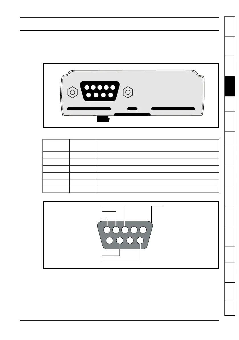
4 Electrical installation
4.1 Terminal descriptions
SI-PROFIBUS has a standard 9-way female D-type connector for the PROFIBUS-DP
network.
Figure 4-1 SI-PROFIBUS terminals
Table 4.1 SI-PROFIBUS D-Type pin out
Figure 4-2 D-Type connections
Control Techniques recommend using connectors approved by PROFIBUS
International at all times.
D-type
Terminal Function Description
3 RxD/TxD-P Positive data line (B) - Red
8 RxD/TxD-N Negative data line (A) - Green
6 + 5V ISO +5 V isolated, use only for termination resistors
5 0V ISO 0 V isolated, use only for termination resistors
4 CNTR-P RTS line
1, Shell Shield Cable shield connection
RxD/TxD-N (Green)
+5 V ISO (for termination only)
5 2 1
79 8 6
Cable screen (braided shield)
0V ISO (for termination only)
Shell
CNTR-P
4 3
RxD/TxD-P (Red)