INNOVATION AND FLEXIBILITY
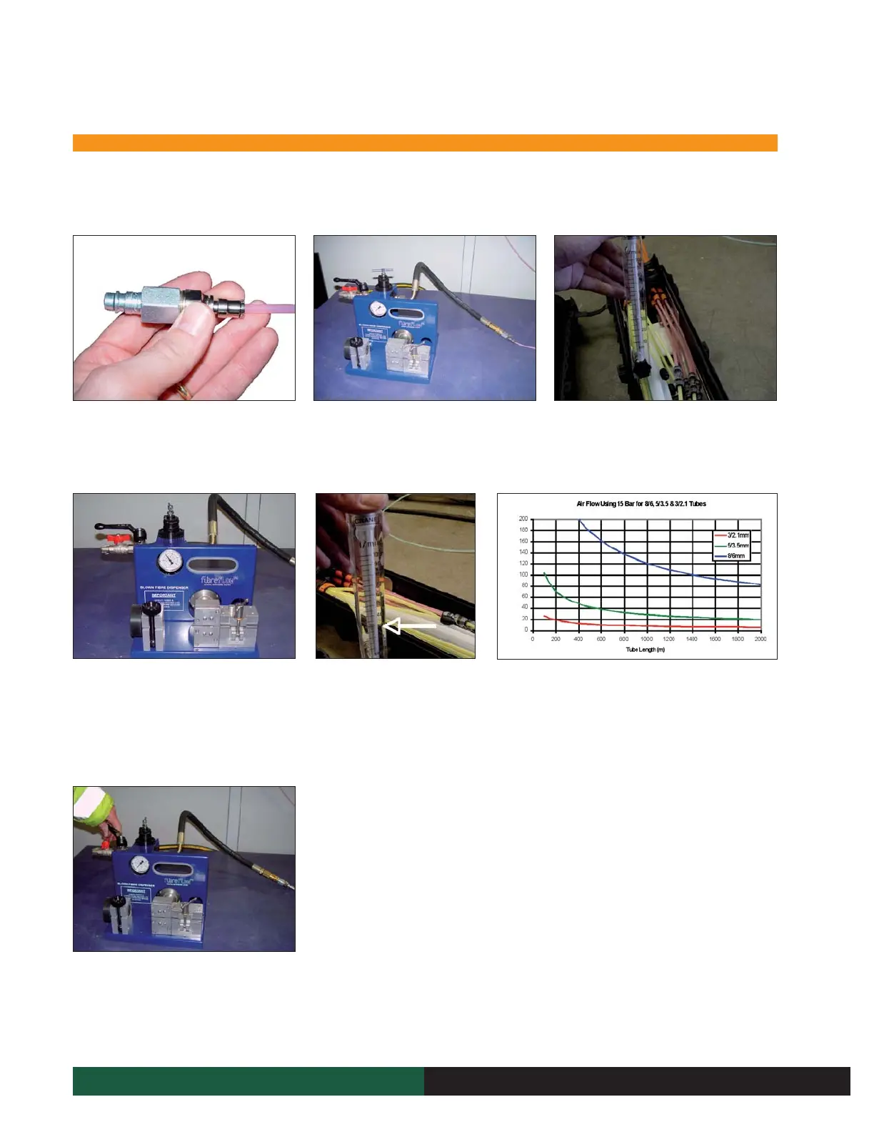
9.11.1 Air Flow Testing
NOTE: The microduct distance is required for this test.
1. Take the hose connector and the 8mm to
5mm reducer from the Air Flow Meter Kit
(code 7778) and connect together.
4. Connect the air compressor to the Dispenser
and turn on the air compressor. Open both
valves on the Dispenser and adjust to the
operating pressure. In this case 10bar is being
used. (10 bar max for internal microducts)
7. Depressurise the microduct by first isolating
the pressure by turning the red valve. Now
vent the air from the microduct by turning the
black lever.
2. Connect microduct number 1 to the Air Hose
on the Dispenser (code 7855).
5. Take a reading of the air flow
from the meter, measuring from
the top of the metal float.
8. Repeat this test with all remaining
microducts BEFORE carrying out
the Pressure & Continuity test. If
the flow is not correct, refer to the
fault finding flow chart.
3. Connect the Air Flow Meter to the
corresponding microduct at the other end
of the route.
6. Check if the airflow reading taken is similar to the one
stated in air flow chart. The distance of the microduct route
is required to do this. Chart found at the end of this section.
NOTE: The airflow does not have to be exactly the same
as that stated on the chart. If the airflow is 3-4 l/min
lower, then this is seen as acceptable.
9 Fibre blowing
“This document is intended as a guide only. Whilst the information it contains is believed to be correct, Emtelle can take no responsibility for actions taken based on the information contained in this document. Emtelle reserves the
right to make changes to this document without notice. All sales of product are subject to Emtelle’s terms and conditions of sale only, which can be found on Emtelle’s website.”
82
INNOVATION AND FLEXIBILITY
 Loading...