“This document is intended as a guide only. Whilst the information it contains is believed to be correct, Emtelle can take no responsibility for actions taken based on the information contained in this document. Emtelle reserves the
right to make changes to this document without notice. All sales of product are subject to Emtelle’s terms and conditions of sale only, which can be found on Emtelle’s website.”
86
INNOVATION AND FLEXIBILITY
THE
INSTALLATION AND MAINTENANCE TRAINING MANUAL
9 Fibre blowing
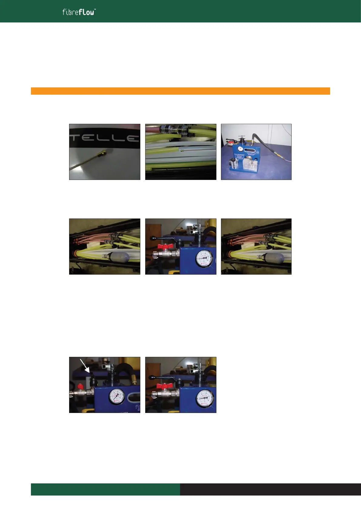
9.11.3 Continuity Test
1. Get a 5cm length of 4 fibre unit
and install a fibre bead onto the
leading edge of the fibre unit.
2. Insert the 5cm fibre length, bead
first into the first microduct to
be tested at the start of the blow
route.
3. Connect the primary m/d to the
Air Hose on the Dispenser using
the hose-to-microduct coupling
found in the kit 820B.
4. Connect the air filter from the
kit 820B onto the corresponding
microduct at the other end of
the route.
5. Connect air compressor to
Dispenser and turn on the air
compressor. Adjust air pressure
to 4 Bar, then Open Inlet valve on
the Dispenser. Both valves are now
in line. DO NOT EXCEED 4 BAR
PRESSURE FOR THIS TEST
6. Wait for The fibre to blow into
the air filter at the other end
of the route (normally under
2 minutes on routes less
than 1000m). It is possible
to see the fibre through the
reducing connector between
the 5mm m/d and the air filter.
DO NOT REMOVE THE AIR
FILTER UNTIL THE FIBRE HAS
EMERGED FROM THE m/d
7. Once the fibre has passed through
the m/d, turn off air compressor
and Purge the air from the
microduct by closing the red lever
and then the black lever as shown.
8. Dump the air from the
compressor side by rotating red
lever back to the open position.
The compressed air will vent
through the black valve.
NOTE: If the fibre does not emerge at the other end of the microduct, refer to the next page for Instructions.
 Loading...