“This document is intended as a guide only. Whilst the information it contains is believed to be correct, Emtelle can take no responsibility for actions taken based on the information contained in this document. Emtelle reserves the
right to make changes to this document without notice. All sales of product are subject to Emtelle’s terms and conditions of sale only, which can be found on Emtelle’s website.”
89
INNOVATION AND FLEXIBILITY
THE
INSTALLATION AND MAINTENANCE TRAINING MANUAL
9 Fibre blowing
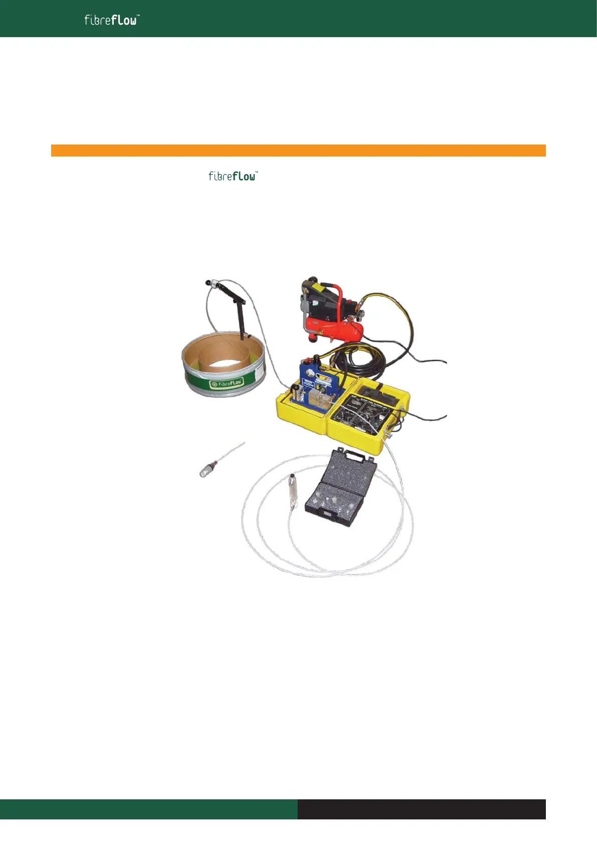
9.12 Blowing equipment for fi bre unit installation
The Blown Fibre process and apparatus is subject to British Telecommunications plc’s patents (European Patent 108590 and other corresponding
foreign and related patents). The process and apparatus have been licensed by BT to Emtelle Ltd and several of the drawings and photographs in
this document are reproduced with BT’s kind permission.
9.12.1 Blowing system Set Up
NOTE: Set shown has power supplied via two generators or internal power source
Blowing Unit 2A (7016)
The Blowing unit consists of two main components: the control box and the blowing head, both contained within a carry case. Each unit will include
the following items on delivery.
■ Remote Control Unit
■ Power lead for 110V ac supply
■ Power Lead for 24 V dc supply
■ Blowing head lead (5m length)
■ 4 Spare drive wheel tyres
■ 2mm diameter silicone rubber seal (0.5m long)
■ 2 Spare buckle detector lenses
■ Roll of 12mm PTFE tape
■ 3mm and 2.5 mm Allen keys for feed wheel cover screws and fibre plates respectively
■ User Instruction sheet for the Blown Fibre Unit 2
Fibre Pan and Fibre unit
Dispenser with Blowing
Head
Air Stone
Blowing Unit
Compressor
Fibre Unit
Primary m/d
Air Flow Meter Kit
 Loading...