INNOVATION AND FLEXIBILITY
THE
INSTALLATION AND MAINTENANCE TRAINING MANUAL
Method:
Ensure that the end of the fibre unit is free from any ragged edges. If there are any ragged edges present, cut
about 20mm off the end of the fibre unit using a sharp knife. Take care when using a sharp knife and dispose of
the off-cut carefully.
Push the blowing bead onto the end of the fibre unit, turning the bead as you do so. The bead will sit on the
end of the fibre unit.
If the bead doesn’t go on easily or won’t go on at all, there must be a ragged edge present on the fibre unit, in
which case you have to repeat the cutting process.
The crimping of the bead requires very little effort, as the side-wall of the bead is very thin. Holding the
bead and fibre unit, gently squeeze the cutters at a distance of about 2mm from the trailing end of the
bead. The cutters will produce small indentations on the bead. To ensure the bead has a good grip, give it
a small tug. If the bead moves, adjust the cutters and repeat the crimping process.
Do not squeeze the bead so hard that it becomes very wide, with two sharp protruding edges.
Remember the bead has to pass freely through small connectors and m/d.
8.9 Fibre Restraint
There are outdoor locations where temperatures vary daily. The inconvenient aspect is that plastics (duct, cable,
microduct) all expand measurably with daily hot/cold cycles, whereas fibre optics do not.
If a plastic tube expands 10mm in the sun, any FU inside it will appear to have shrunk back into the tube. Even if the
tube is held at both ends, its middle portion can expand and cause the FU to retract.
Now imagine a fibre tray with this same effect in progress. Fibres will try to pull out of the tray, and go tight
around the bend manager corners. Then if later the effect is reversed, the fibre will try to push back to where
it was, and fail, due to its high tendency to buckle. Fibre will push right off the tray and cause pressures and
microbend problems etc.
This tray (shown right) shows the tangle that can result from thermal changes together with fibre that is free to move.
If we now secure fibres at selected locations, they will be prevented from suffering the fate of the tray shown.
There may still occur some changes in m/d length, but these will no longer result in fibres causing problems in
the tray. The approved methods are described below.
8.9.1 Lock & Block
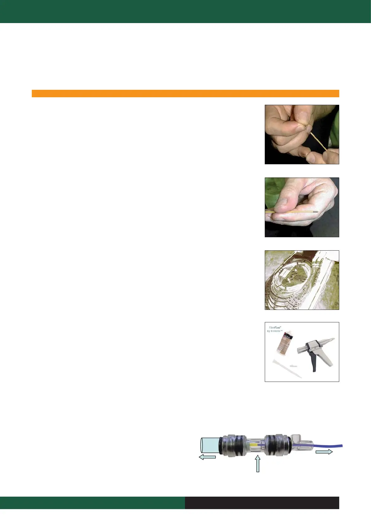
L&B consists of a stem that fits into a connector. Resin is injected into this to secure and seal the FU at this connector.
Consequently L & B also serves as a blocking point, eliminating waterblock or gasblock connectors.
A Practicality:
In many cases the L&B stem can be fitted onto the m/d AFTER the blowing stage, since the L&B is normally at the end of a m/d length. In some cases,
it may be necessary to fit the stem BEFORE the blow, and later blow through m/d and stem. The individual situation will dictate which method is used.
In common with all Emtelle Fibre Restraint methods, the fibre unit sheath
(yellow in the photograph on the right) must be removed to allow the
restraint device to grip directly onto the acrylate fibre bundle. Failure to do
this will be detrimental in terms of water blocking and restraining force.
8 Fibre Units And Fibre Handling
“This document is intended as a guide only. Whilst the information it contains is believed to be correct, Emtelle can take no responsibility for actions taken based on the information contained in this document. Emtelle reserves the
right to make changes to this document without notice. All sales of product are subject to Emtelle’s terms and conditions of sale only, which can be found on Emtelle’s website.”
71
INNOVATION AND FLEXIBILITY
Lock & Block
To Splice Trays
(Fibre Sheath
Removed)
Fibre Sheath
Removed from this
Point Onwards
Microduct
Storage
 Loading...