Cerabar PMP21 IO-Link Electrical connection
Endress+Hauser 17
6 Electrical connection
6.1 Connecting the measuring unit
6.1.1 Terminal assignment
L
WARNING
Risk of injury from the uncontrolled activation of processes!
‣
Switch off the supply voltage before connecting the device.
‣
Make sure that downstream processes are not started unintentionally.
L
WARNING
An incorrect connection compromises electrical safety!
‣
In accordance with IEC/EN 61010, a suitable circuit breaker must be provided for the
device.
‣
Non-hazardous area: To meet device safety specifications according to the IEC/EN
61010 standard, the installation must ensure that the maximum current is limited to
500 mA.
‣
Protective circuits against reverse polarity are integrated.
NOTICE
Damage to analog input of PLC resulting from incorrect connection
‣
Do not connect the active PNP switch output of the device to the 4 to 20 mA input of a
PLC.
Connect the device in the following order:
1. Check whether the supply voltage matches the supply voltage indicated on the
nameplate.
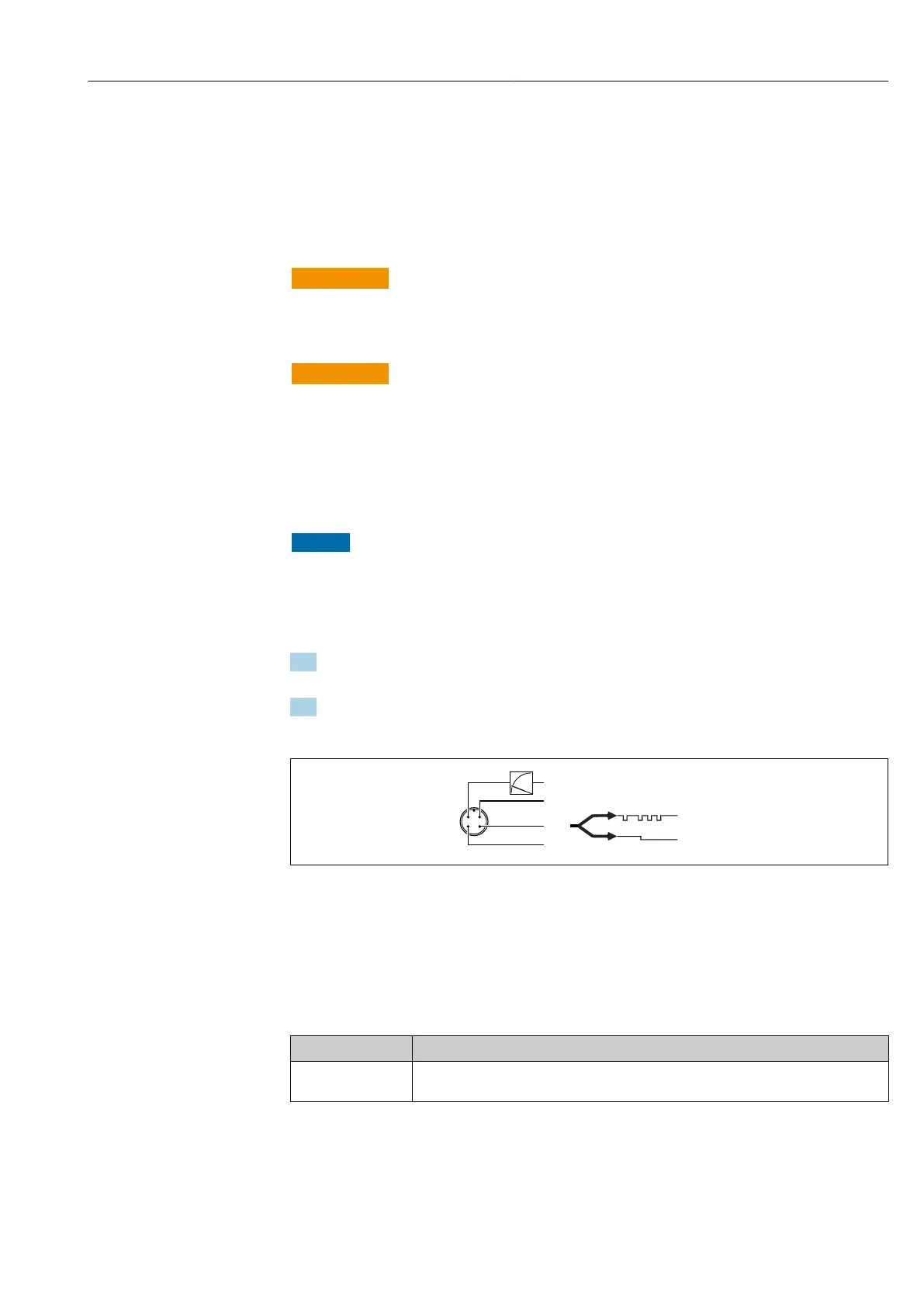
2. Connect the device as indicated in the following diagram.
Switch on the supply voltage.
A0034006
1 M12 plug
1 Supply voltage +
2 4-20 mA
3 Supply voltage -
4 C/Q (IO-Link communication or SIO mode)
6.1.2 Supply voltage
Electronic version Supply voltage
IO-Link 10 to 30 V
DC
IO-Link communication is guaranteed only if the supply voltage is at least 18 V.