Electrical connection Cerabar PMP21 IO-Link
18 Endress+Hauser
6.1.3 Current consumption and alarm signal
Electronic version Current consumption Alarm signal
1)
IO-Link Maximum current consumption: ≤ 300 mA
1) For MAX alarm (factory setting)
6.2 Connection data
6.2.1 Switching capacity
• Switch status ON: I
a
≤ 200 mA
1) 2)
; Switch status OFF: I
a
≤1 mA
• Switch cycles: >10,000,000
• Voltage drop PNP: ≤2 V
• Overload protection: Automatic load testing of switching current;
• Max. capacitance load: 1 μF at max. supply voltage (without resistive load)
• Max. cycle duration: 0.5 s; min. t
on
: 40 μs
• Periodic disconnection from protective circuit in the event of overcurrent (f = 2 Hz) and
"F804" displayed
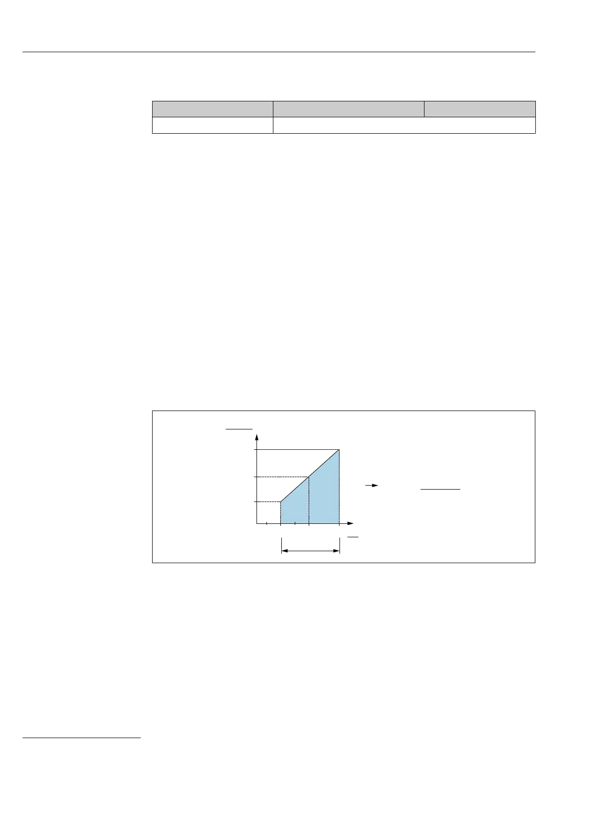
6.2.2 Load (for 4 to 20 mA devices )
In order to guarantee sufficient terminal voltage, a maximum load resistance R
L
(including
line resistance) must not be exceeded depending on the supply voltage U
B
of the supply
unit.
[ ]W
20 30
10
0
1022
587
152
U
[V]
1
2
R
R
L
L
max
max
A0031107
1 Power supply 10 to 30 V
DC
2 R
Lmax
Maximum load resistance
U
B
Supply voltage
If load is too great:
• Failure current is indicated and "S803" displayed (indication: MIN alarm current)
• Periodic checking to establish if it is possible to quit fault state
• In order to guarantee sufficient terminal voltage, a maximum load resistance RL
(including line resistance) must not be exceeded depending on the supply voltage UB of
the supply unit.
1) For the switch output 1 x PNP + 4 to 20 mA output 100 mA can be guaranteed over the entire temperature range. For lower ambient
temperatures, higher currents are possible but cannot be guaranteed. Typical value at 20 °C (68 °F) approx. 200 mA. For the switch output "1 x
PNP", 200 mA can be guaranteed over the entire temperature range.
2) Larger currents are supported, thus deviating from the IO-Link standard.