1
OVERVIEW ..........................................................................................................................................................4
1.1
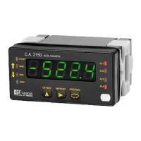
Introduction to model CA2150-E ................................................................................................................................4
2
GETTING STARTED..............................................................................................................................................5
2.1
Power Supply and connectors ....................................................................................................................................9
2.2
Wiring overview ...................................................................................................................................................... 10
2.3
Instrument front view.............................................................................................................................................. 11
3
INPUT PROGRAMMING.....................................................................................................................................12
3.1
DC/ AC VOLTAGE INPUT WIRING (RANGES: 2, 20, 200, 600 V)................................................................................ 13
3.2
1 or 5 DIRECT AMPERES INPUT WIRING ................................................................................................................. 14
3.3
200 mA INPUT WIRING........................................................................................................................................... 15
3.4
CURRENT TRANSFORMER 1A / 5A AC WIRING....................................................................................................... 16
3.5
SHUNT 50/ 60/ 100 mV DC/ AC WIRING.................................................................................................................. 17
4
DISPLAY PROGRAMMING .................................................................................................................................18
4.1
Scale ...................................................................................................................................................................... 19
4.1.1
Description menu configuration Display ............................................................................................................. 20
5
KEYBOARD AND CONNECTOR FUNCTIONS.......................................................................................................22
5.1
Keyboard functions.................................................................................................................................................. 22
5.2
Connector functions ................................................................................................................................................ 24
5.2.1
Logic functions diagram.................................................................................................................................... 25
5.2.2
Table of programmable functions...................................................................................................................... 26
5.2.3
Programming the functions............................................................................................................................... 27
6
PROGRAMMING LOCK OUT BY SOFTWARE.......................................................................................................28
6.1
Security menu diagram............................................................................................................................................ 29
7
OUTPUT OPTIONS.............................................................................................................................................32
7.1
Setpoints output...................................................................................................................................................... 34
7.1.1
Introduction ..................................................................................................................................................... 34
7.1.2
Description of operation.................................................................................................................................... 35
7.1.3
Installation....................................................................................................................................................... 36
7.1.4
Wiring.............................................................................................................................................................. 36
7.1.5
Technical specifications..................................................................................................................................... 37
7.1.6
Setpoints menu diagram ................................................................................................................................... 38
7.1.7
Direct access to the setpoints value programming ............................................................................................. 39