7.1.3 Installation
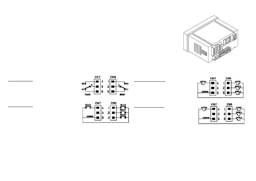
7.1.4 Wiring
Lift out the electronics assembly from the case and use a screw-
driver to push on the junctions
between
the case and the shadow areas to detach them from the case. See fig. The so
performed orifice will allow any of the setpoints 2 Relays SPDT, 4 Relays SPST, 4 Output NPN
or 4 Output PNP. ) board output connectors be brought out at the rear of the instrument
option is installed by plugging the connector in the main board location. Insert the card pin in
the corresponding main board slot and push down to attach both connectors.
If the instrument is to be installed in high vibrating environments, it is rec
the card to the main board making use of the copper tracks on both sides of the card pin and
around the main board hole on its solder side.
PIN 4 = NO2 PIN 1 = NO1
PIN 5 = COMM2 PIN 2 = COMM1
PIN 6 = NC2 PIN 3 = NC1
4 RELAYS OPTION
PIN 4 = RL4 PIN 1 = RL1
PIN 5 = N/C PIN 2 = RL2
PIN 6 = COMM PIN 3 = RL3
PIN 4 = OP4 PIN 1 = OP1
PIN 5 = N/C PIN 2 = OP2
PIN 6 = COMM PIN 3 = OP3
4 OPTOS PNP OPTION
PIN 4 = OP4 PIN 1 = OP1
PIN 5 = N/C PIN 2 = OP2
PIN 6 = COMM PIN 3 = OP3