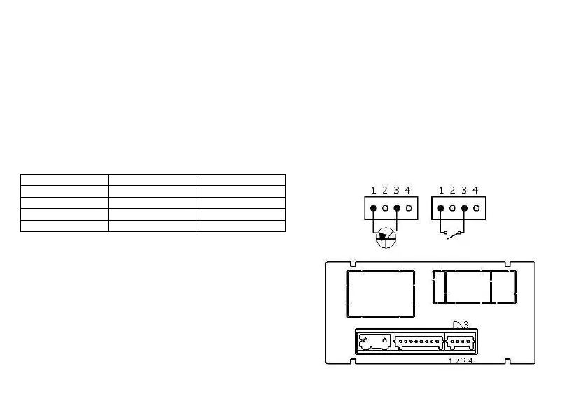
5.2 Connector functions
The connector CN3 provides 3 optocoupled inputs that can be operated from contacts logic levels supplied by an external
electronic system. Three different functions may be then added to the functions available from the front panel keys. Each function
is associated to a pin (PIN 2, PIN 3 y PIN 4) that is activated applying a low level, in each one, with respect to PIN 1 or COMMON.
The association is achieved through the programming of a number between 0 and 16 corresponding to one of the functions listed
in the following table.
• Factory configuration
As shipped from the factory, the CN3 connector allows the PEAK and VALLEY functions operated from the front-panel keyboard
and moreover incorporate the HOLD function.
When a HOLD is made, the display value remains frozen while the corresponding pin is activated. The HOLD state, affects neither
the instrument internal operation nor the analog and setpoint outputs.
CN3 : FACTORY CONFIGURATION Logic functions diagram
PIN (INPUT) Function Number
PIN 1 COMMUN
PIN 2 (INP-1) PEAK Function nº 3
PIN 3 (INP-2) VALLEY Function nº 4
PIN 4 (INP-3) HOLD Function nº 6
The external electronics applied to the CN3 co
must be capable of withstanding a potential of 40 V/ 20 mA
present at all terminals with respect to COMMON. In order
to guarantee the electromagnetic compatibility please refer
to the connection instructions given on Page 9.