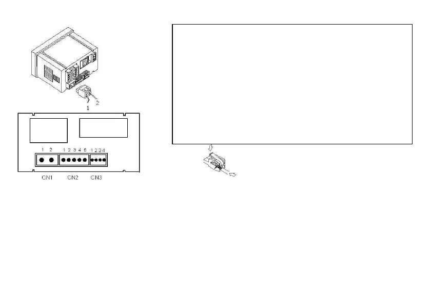
2.1 Power Supply and connectors
WIRING and POWER SUPPLY RANGE
CA2150-E1
85 V – 265 V AC 50/ 60 Hz ou 100 – 300 V DC
CA2150-E2
22 – 53 V AC 50/ 60 Hz ou 10,5 - 70 V DC
Borne 1: Phase
Borne 2: Neutral
NOTE: When DC power supply (direct)
polarity in connector CN1 is indistinct.
WARNING: If not installed and used in accordance with these
instructions, protection against hazards may be impaired.
In order to guarantee the electromagnetic compatibility, the following
guidelines should be kept in mind:
Power supply wires may be routed separated from signal wires.Never run
power and signal wires in the same conduit.Use shielded cable for signal
wiring and connect the shield to the ground of the indicator. The cables
section should be >0.25 mm
2
INSTALLATION
To meet the requirements of the directive EN61010
-
permanently connected to the mains supply, it is obligatory to install a circuit
breaking device easy reachable to the operator and clearly marked
disconnect device
.
CONNECTEURS
CN1
To perform wiring connections, strip the wire leaving from 7 and 10 mm
exposed to air and insert it in the proper terminal while pushing the fingertip
down to open the clip inside the connector as indicated in the figures.
Each terminal accep
ts cables of section between 0.08 mm² and 2.5 mm² (AWG
CN2 et CN3
To perform wiring conections, strip the wire leaving from 5 and 6
mm exposed to air and insert it in the proper terminal while pushing the finger
down to open the clip inside the connector as indicated in the figures.
CN2
Each terminal accepts cables of section between 0.08 mm² and 1.5 mm²
(AWG 28 ÷ 14).
CN3
Each terminal accepts cables of section between 0.08 mm² and 0.5 mm²
(AWG 28 ÷ 20).