ENGBO AS – et selskap i Engbo-gruppen
BESØKSADRESSE: Wirgenesvei 7, 3157 Barkåker POSTADR: Postboks 2288 Postterminalen, 3103 Tønsberg
E-MAIL: support@engbo.no WEB: www.engbo.no TLF: +47 33 00 31 50 FAKS: +47 33 00 31 60
Electrical wiring
The label on the cover of the electronic unit also shows a diagram for connecting the electrical
cables, - but always verify correct connections with wiring diagram.
IMPORTANT
Always switch off the power at the main switch and/or disconnect the battery
before working on the wiring connections.
Switch panel
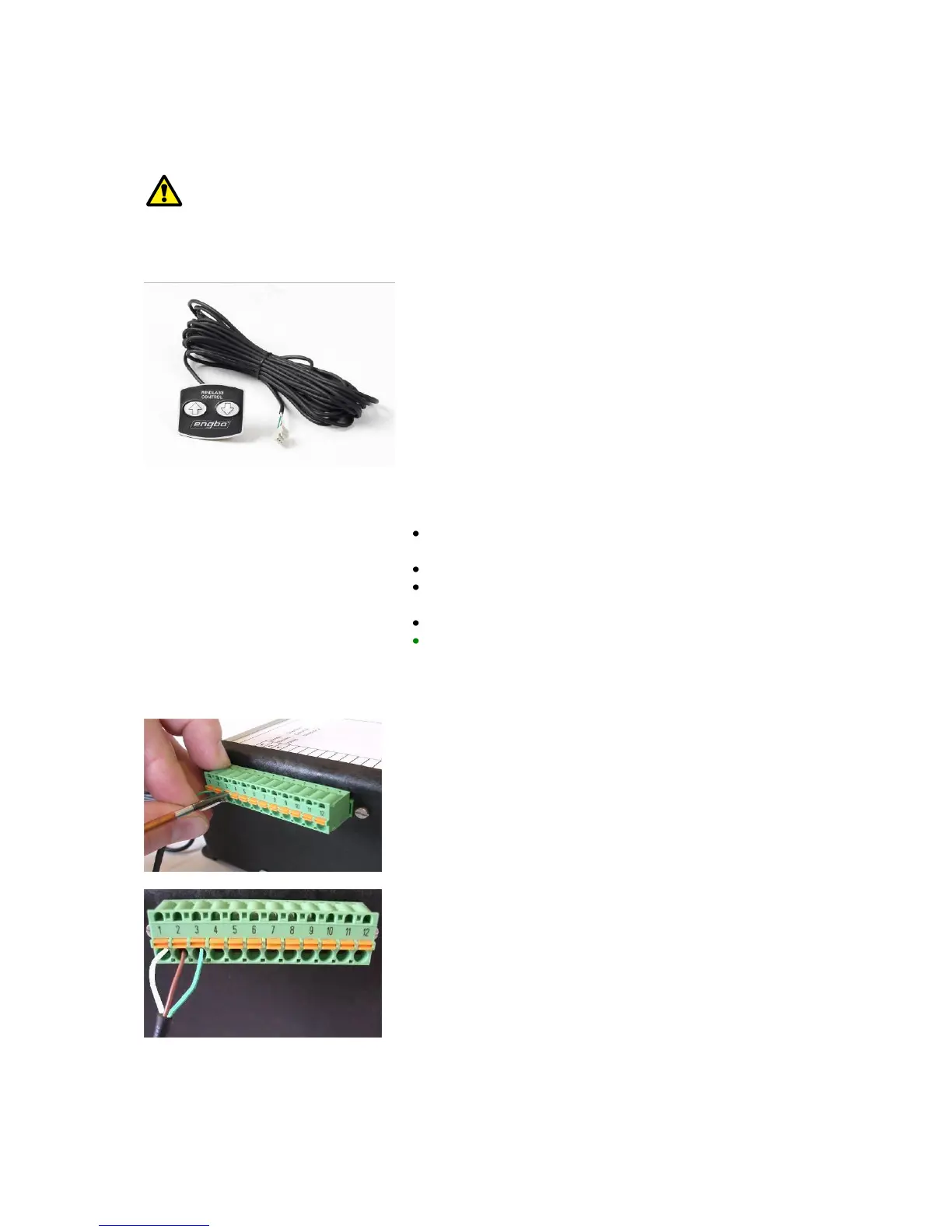
Standard touch panel (Item no. 12-79000)
The windlasses are supplied as standard with 1 x
watertight touch panel for installing in a readily accessible
place in the cockpit.
If only this touch panel is to be fitted, it must, for safety
reasons, be positioned so as to allow the operator a clear
view of the anchor as it is raised and seated in the anchor
bracket.
The panel comes with a self-adhesive surface, but if you
prefer, you can use the corner holes to screw it firmly in
position.
Drill an hole (dia. 18 mm) in the place where the panel
is to be fitted.
Run the panel cable through the hole.
Remove the protection tape from the rear surface of
the panel and affix the panel firmly to the surface.
Run the cable to the electronic control box.
Cut off any surplus cable and strip the ends of the
three wires that are to be connected to the terminal
clips as described in the connection diagram. (Picture
of control box).
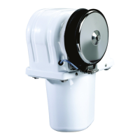
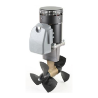
Connecting the switch panel
The windlasses are supplied as standard with one switch
panel and 10 m of cable. Cut the wires to the required
length and strip approx. 10 mm from their ends. Twist
the wires in the separate cables and attach the cables to
the green terminal box by pressing in the orange button
above the appropriate hole and keeping it depressed
while you insert the cable. Release the button once the
cable is in place. Check that the cable is seated firmly
and that the insulation is inside the terminal clip so that
no loose wires are sticking out.
Connect the cables as follows:
1: White
2: Brown
3: Green
If you wish to connect additional panels, connect the
cables in parallel to 1, 2 and 3. (2 is the common 0 V).
(Spring-lock terminal clips have been chosen rather than
screw clips to prevent problems linked to vibrations
and/or changes in temperature causing the clips to
loosen).