ENGBO AS – et selskap i Engbo-gruppen
BESØKSADRESSE: Wirgenesvei 7, 3157 Barkåker POSTADR: Postboks 2288 Postterminalen, 3103 Tønsberg
E-MAIL: support@engbo.no WEB: www.engbo.no TLF: +47 33 00 31 50 FAKS: +47 33 00 31 60
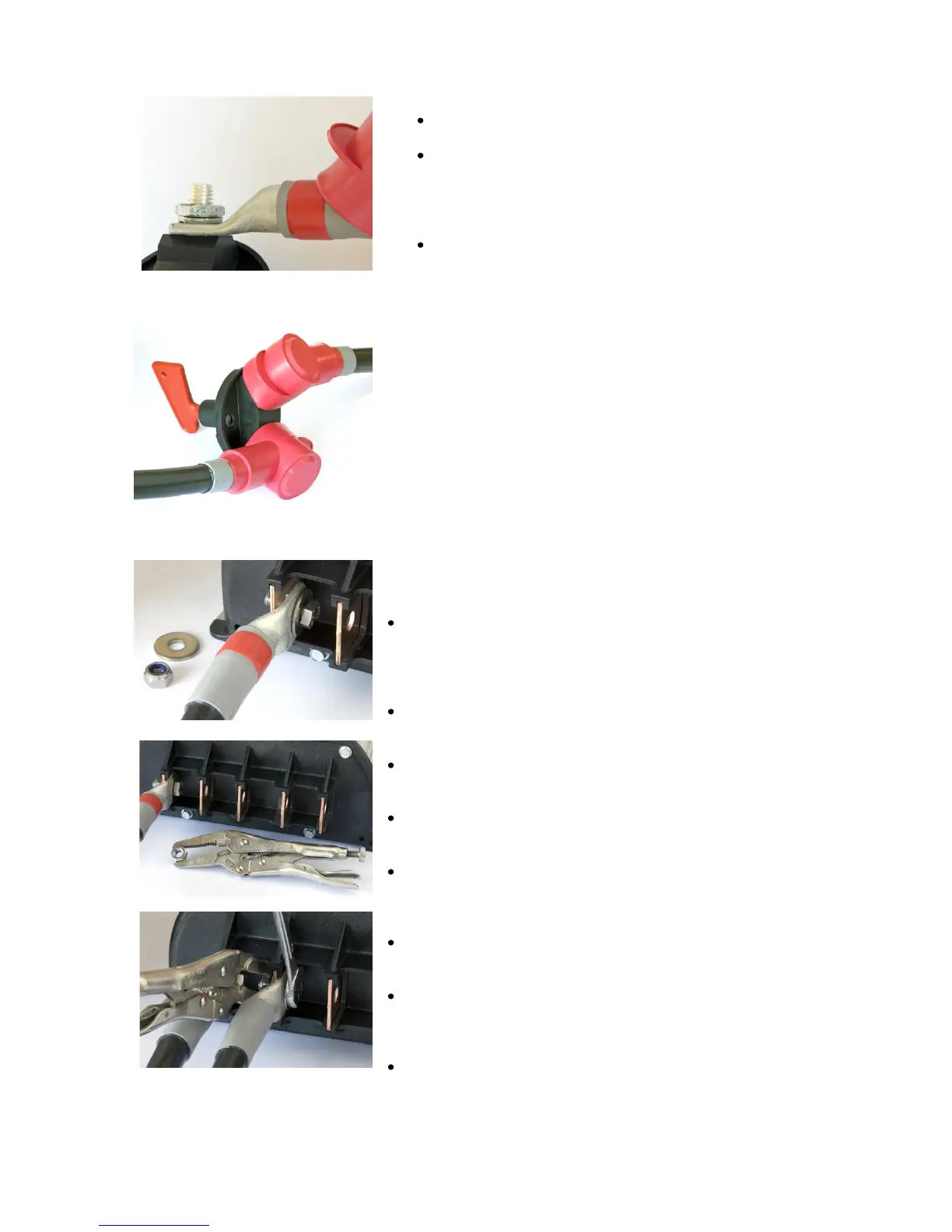
Main switch connection
The bolt itself is an active current conductor.
The pictures show a correct main switch connection.
Please note that the cable-lug is mounted directly
onto the terminal post, washer and nut is on top of
the cable-lug.
Different kinds of main switches with different kinds
of terminals exist. Correct torque is;
M8 Brass: 10 Nm
M10 Brass: 15 Nm
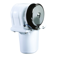
The picture shows isolating rubber-caps mounted on both
terminals. (For improved understanding, the interrupter is
not mounted on a wall.)
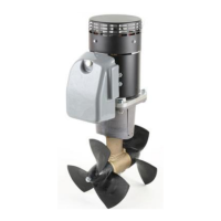
Control box connections
Tips for mounting:
Pre-cut correct cable-lengths and mount cable-lugs in
advance so mounting the cables on the box can be done
in a comfortable position before the unit is mounted in
the boat.
One will need 2 pcs 13mm spanners to secure the M8-
bolts.
A long-nosed VISE-GRIP plier may be useful to hold the
nut.
Correct torque is 20 Nm for the Stainless Steel bolts,
(A4).
Always begin the mounting/assembly from the left,
entering the bolt with a big washer into the hole from the
right.
All cable-lugs shall always be on the right side, in
direct contact with the copper-bar.
Use M8x20mm bolts for copper-bars number; 1, 2, 3, and 5
and M8x25mm for bar number 4. It shall also be mounted a
plain washer between cable-lug and lock-nut.
Mount the three first cables with the cable-lugs pointing in the
same direction, as shown in the pictures.