132
WSG-1068 ENGINE
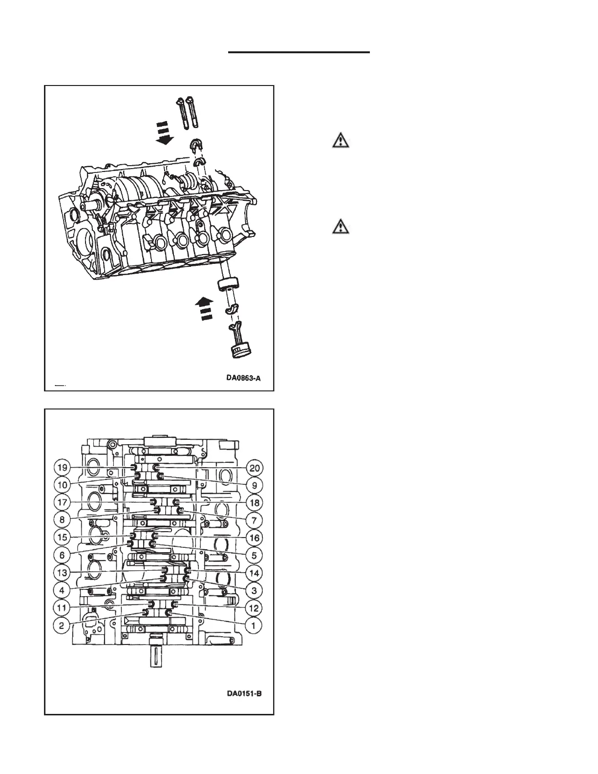
11. Use the Connecting Rod Guide Tool and Piston Ring
Compressor to install the piston and connecting rod
assembly.
12.
CAUTION: Do not scratch the cylinder walls
or crankshaft journals with the connecting rod
(6200).
Once the connecting rod is seated on the crankshaft
journal, remove the connecting rod guide tools.
13.
CAUTION: The rod cap installation must
keep the same orientation as marked during
disassembly.
NOTE: The connecting rod caps are of the “cracked’’
design and must mate with the connecting rod ends.
Excessive bearing clearance will result if not mated
properly.
Install the connecting rod bearings, position the
connecting rod cap and loosely install the two new
bolts.
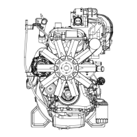
14. NOTE: Be sure to tighten the bolts in two stages.
Tighten the connecting rod bolts in the sequence
shown.
Stage 1: Tighten to 40-45 Nm (30-33 lb/ft).
Stage 2: Tighten an additional 90 degrees to 120
degrees.
15. Rotate the crankshaft and repeat the procedure to
position each connecting rod at bottom dead center
until all bolts are tightened to specification.