160
WSG-1068 IGNITION SYSTEM
GENERAL INFORMATION
NOTE: Whenever a wire is labeled with two colors, the
first color listed is the basic color of the wire, and the
second color listed is the stripe marking of the wire.
How to Find Electrical Concerns
Troubleshooting Steps
These six steps present an orderly method of
troubleshooting.
Step 1: Verify the concern.
Operate the complete system to check the
accuracy and completeness of the customer’s
complaint.
Step 2: Narrow the concern.
Using a DVOM, narrow down the possible
causes and locations of the concern to pinpoint
the exact cause.
Read the description about the components and
study the wiring schematic. You should then
know enough about the circuit operation to
determine where to check for the trouble.
Step 3: Test the cause.
Use electrical test procedures to find the specific
cause of the symptoms.
Step 4: Verify the cause.
Confirm that you have found the correct cause
by connecting jumper wires and/or temporarily
installing a known good component and
operating the circuit.
Step 5: Make the repair.
Repair or replace the inoperative component.
Step 6: Verify the repair.
Operate the system as in Step 1 and check that
your repair has removed all symptoms without
creating and new symptoms.
Troubleshooting Tools
Jumper Wire
This is a test lead used to connect two points of a circuit.
A Jumper Wire can bypass an open in a wire to
complete
a circuit.
WARNING: NEVER USE A JUMPER WIRE
ACROSS LOADS (MOTORS, ETC.) CONNECTED
BETWEEN HOT AND GROUND. THIS DIRECT
BATTERY
SHORT MAY CAUSE INJURY OR FIRE.
Voltmeter
A DC Voltmeter measures circuit voltage. Connect
negative
(- or black) lead to ground, and positive (+ or red) lead to
voltage measuring point.
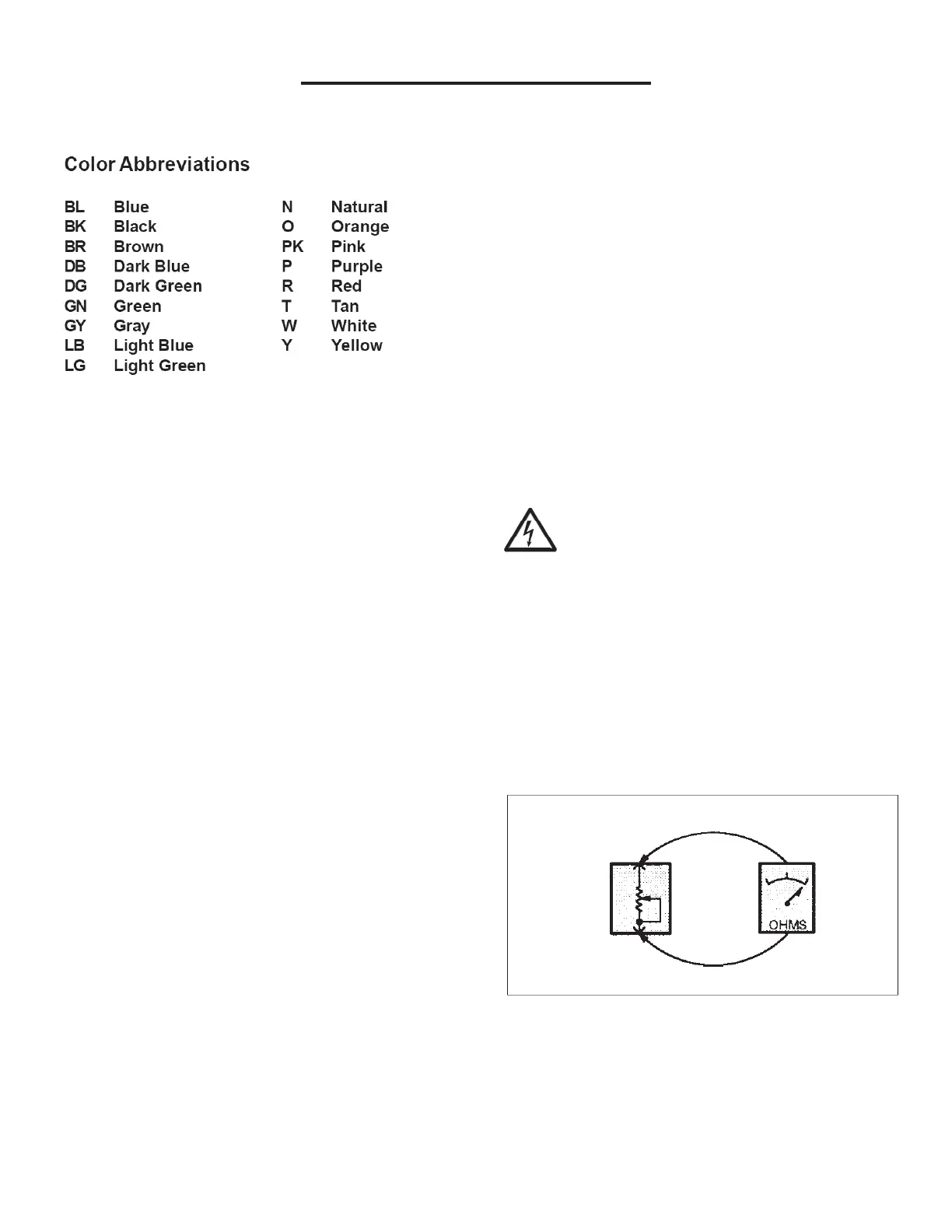
Ohmmeter
Figure 1 – Resistance Check
An Ohmmeter shows the resistance between two
connected points (Figure 1).