225
WSG-1068 CHARGING SYSTEM
Visual Inspection
Preliminary checks to the charging system should be
made regardless of the fault condition. These checks
include:
1. Check battery posts and cable terminals for
clean and tight connections. Clean the posts and
the cables to ensure good electrical contact.
2. Check for secure connections at the generator
output, regulator, and engine ground. Also check
the connection at the load distribution point
(starter relay).
3. Check the fuses/fuse links and wiring to the
generator to ensure that they are not burned or
damaged. This condition, resulting in an open
circuit or high resistance, can cause erratic or
intermittent charging system concerns.
4. Check the battery voltage. If the voltage is less
than 12.3 volts with the engine and all
accessories off, charge battery before
proceeding.
In order to check the generator, the use of Rotunda
Starting and Charging System Tester 078-00005 (VAT-
40) [Rotunda Tools (1-800-578-7375)] or equivalent, is
recommended.
Generator Output Test
NOTE: Refer to the test equipment user’s manual for
complete directions on examining the charging system.
1. Switch the tester to ammeter function.
2. Connect the positive and negative leads of the tester
to the battery.
3. Connect current probe to generator B+ output lead
Circuit 38 (BK/O) (to measure generator output).
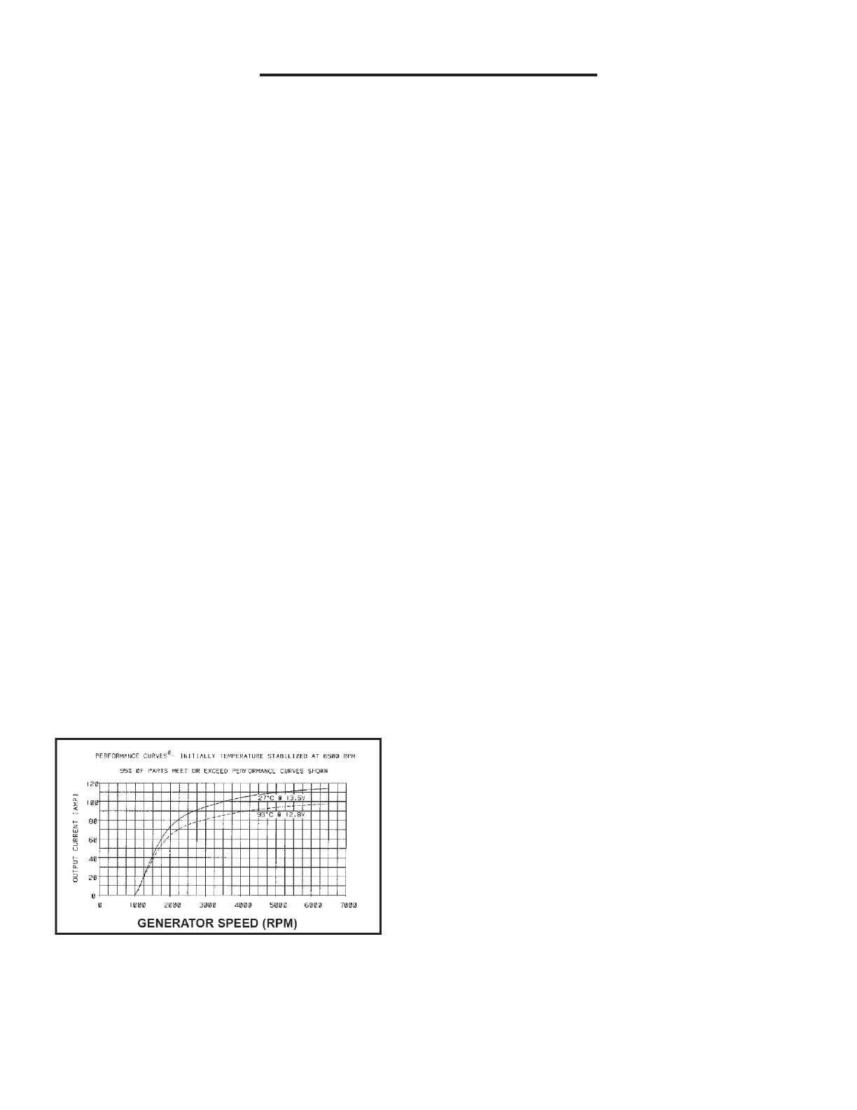
4. With the engine running at 2000 rpm, adjust the VAT-
40 or equivalent load bank to determine the output of
the generator. Generator output should be greater
than values given in graph below. If not, refer to
symptom chart in this Section
Generator Voltage Test
1. Switch the tester to the voltmeter function.
2. Connect the positive lead to the generator A-
terminal connector and the negative lead to
ground.
3. Turn off all electrical accessories.
4. With the engine running at 2000 rpm, check the
generator voltage.
5. Voltage should be between 13.0-15.5 volts.
NOTE: If voltage is not within specifications,
refer to symptom chart.
Battery — Drain Test
WARNING: DO NOT ATTEMPT THIS TEST ON A
LEAD-ACID BATTERY THAT HAS RECENTLY BEEN
RECHARGED. EXPLOSIVE GASES MAY CAUSE
PERSONAL INJURY. FAILURE TO FOLLOW THESE
INSTRUCTIONS MAY RESULT IN PERSONAL
INJURY.
CAUTION: To prevent damage to the meter, do not
crank the engine or operate accessories that draw
more than 10A.
NOTE: No accessory system should have more
than a 50 mA (0.050 amp) draw.
NOTE: Many modules draw 10 mA (0.010 amp) or
more continuously.
NOTE: Use an in-line ammeter between the
battery positive or negative post and its respective
cable.
NOTE: Typically, a drain of approximately one
amp can be attributed to a lamp staying on
continually. Other component failures or wiring
shorts may be located by selectively pulling fuses
to pinpoint the location of the current drain. When
the current drain is found, the meter reading will
fall to an acceptable level. If the drain is still not
located after checking all the fuses, it may be due
to the generator.
NOTE: To accurately test the drain on a battery, an
in-line digital ammeter must be used. Use of a test
lamp or voltmeter is not an accurate method.