Connecting AC and PoE Power
SecureStack B2 Installation Guide 3-15
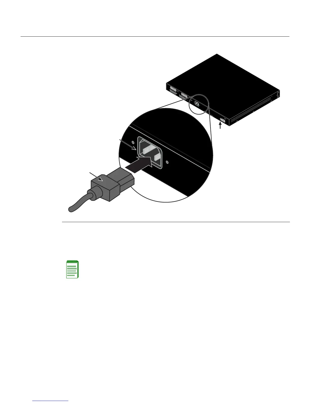
Figure 3-10 Connecting AC Power and RPS
3. ObservethepowerCPULED(notshown)locatedonthefrontpanel.Duringthe
initialization,theCPULEDwillstartbyilluminatingsolidamber,thenstartblinking
green,thenblinkingamber,thenblinkinggreenagainunt iltheendofthe
initialization,andthenturnssolidgreen.
Iftheswitchis
astandaloneunit,itwilltakeapproximately30 secondsfortheswitch
tostartup.IftheswitchisastackManager,itcantakeupto3minutesormoretostart
up,dependingonthenumberofMemberswitchesinthestack.
1 AC power cord 2 AC power connector 3 Connector for external redundant power supply
Note: If the CPU LED illuminates solid red, there was a critical failure. For more
information about the LED indications and troubleshooting, refer to Chapter 4. If you need
additional help, contact Enterasys Networks. Refer to “Getting Help” on page 1-8 for
details.
R
e
d
u
n
d
a
n
t
P
o
w
e
r
S
u
p
p
l
y
D
C
L
i
n
e
-
5
0
V
/
7
.
5
A
M
A
X
,
+
1
2
V
/
1
0
.
5
A
M
A
X
A
C
L
I
N
E
1
0
0
-
2
4
0
V
A
C
5
0
-
6
0
H
z
7
.
5
A
M
A
X
MA
C A
DDR
ESS
SERIAL NO.
S
T
A
C
K
U
P
S
T
A
C
K
D
O
W
N
AC LINE
100-240 VAC
50-60 Hz
7.5 A MAX
À
Á
Â