Connecting to the Network
3-22 Hardware Installation
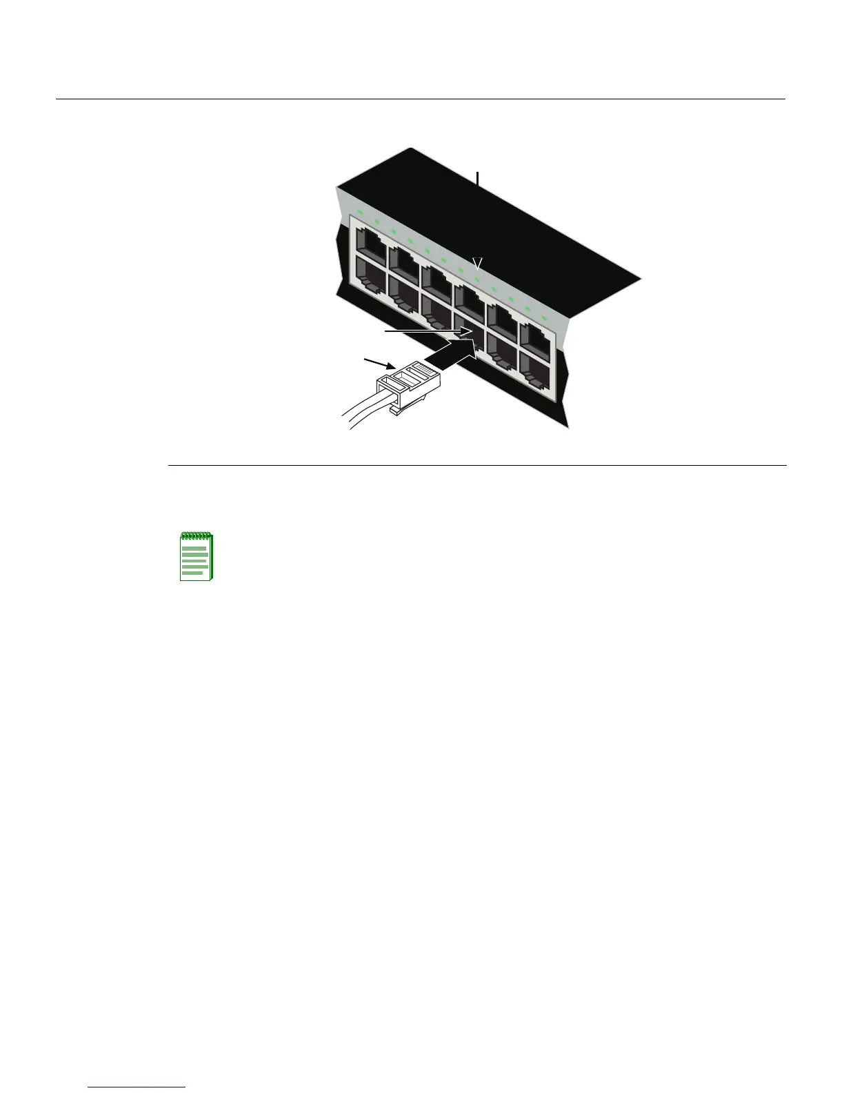
Figure 3-15 Connecting a UTP Cable Segment to RJ45 Port
3. VerifythatalinkexistsbycheckingthattheLink/ActivityLEDisON(solidgreenor
blinkinggreen).
4. IftheLink/ActivityLEDisOFF,performthefollowingstepsuntilitison:
a. VerifythatthecablingbeingusedisCategory 5orbetterwithanimpedance
between85and111 ohmswitha
maximumlengthof100meters(328feet).
b. Verifytha tthedeviceattheotherendofthetwistedpairsegmentisonand
properlyconnectedtothesegment.
c. VerifythattheRJ45connectorsonthetwistedpairsegmenthavetheproper
pinoutsandcheckthecableforcontinuity.Typically,acrossover
cableisused
betweenhubdevices.Astraight‐throughcableisusedtoconnectbetween
switchesorhubdevicesandanenduser(computer).RefertoFigure 3‐16and
Figure 3‐17forfour‐wireRJ45connections.RefertoFigure 3‐18andFigure 3‐19
foreight‐wireRJ45connections.
d. Ensurethatthe
twistedpairconnectionmeetsthedBlossandcablespecifications
outlinedintheCablingGuide.Referto“RelatedDocuments”onpage xvifor
informationonobtainingthisdocument.
5. Ifalinkisnotestablishedorthere isnoPoEpower,contactEnterasys Networks.Refer
to“GettingHelp”onpage 1‐8for
details.
Repeatallstepsaboveuntilallconnectionshavebeenmade.
1 RJ45 connector 2 Port 8 3 Port 8 Link/Activity LED
Note: If the cable is connected to one of the PoE RJ45 front panel ports, solid green or
blinking green also indicates that PoE power is available. If the LED is solid amber or
blinking amber PoE power failed. For more details, refer to Chapter 4.
1
2
1
2
3
4
5
6
7
8
9
10
11
12
11
12
Â
À
Á