Installing Optional Mini-GBICs
3-4 Hardware Installation
Installation
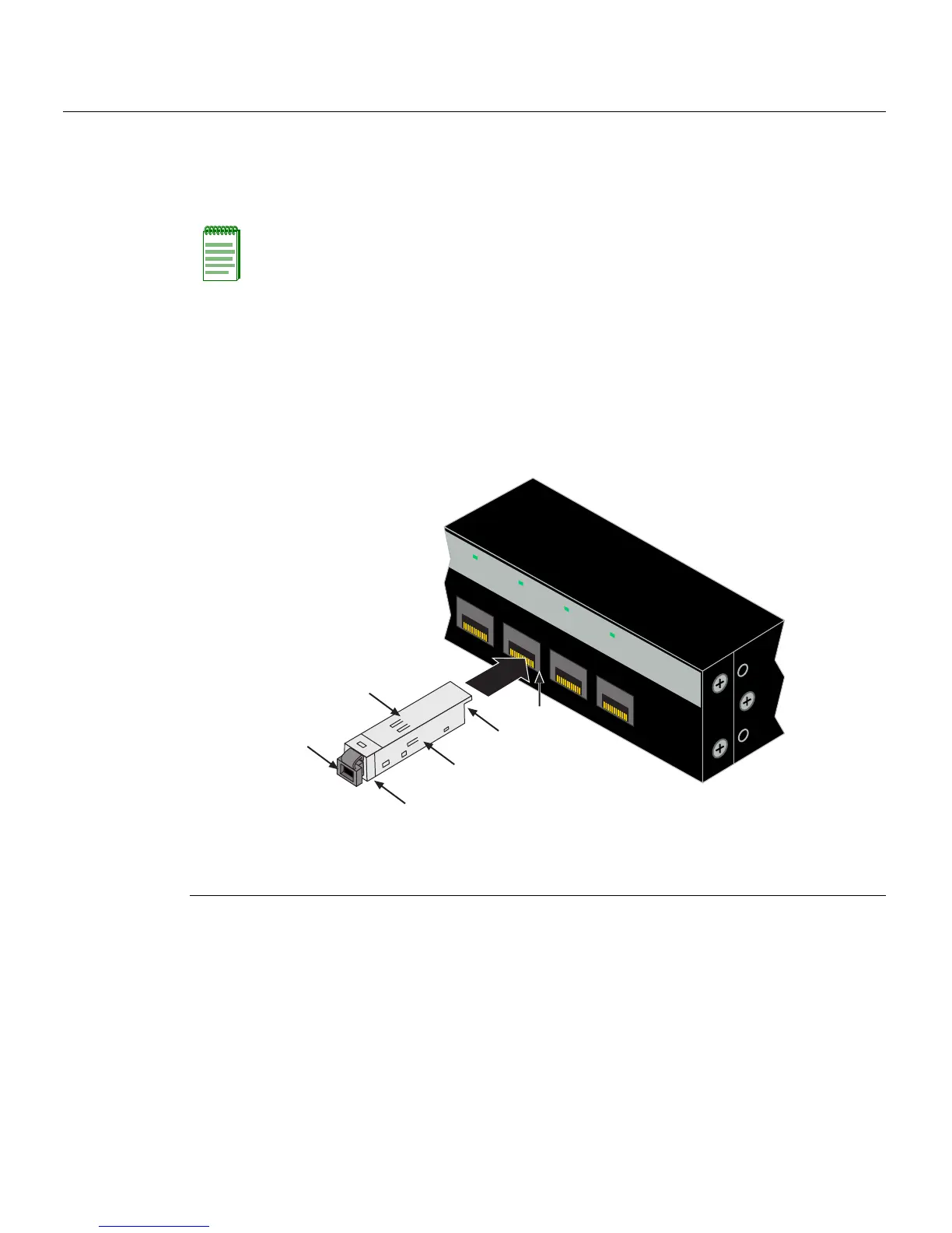
ToinstallaMini‐GBICthathasanMT‐RJconnector,refertoFigure 3‐1,orforaMini‐GBIC
withanLCconnector,refertoFigure 3‐2,andproceedasfollows:
1. HoldtheMini‐GBICwiththetopsidepositionedasshown,andthe7‐pinedge
connectorfacing
theportslot.
2. AligntheMini‐GBICwiththeportslot.
3. PushtheMini‐GBICintotheportslotuntiltheMini‐GBIC“clicks”andlocksinto
place.
Figure 3-1 Mini-GBIC with MT-RJ Connector
Note: If the Mini-GBIC is one with an RJ45 connector (not shown), the installation
procedure is the same as described below. However, the Mini-GBIC has a wire handle to
release it.
1 Mini-GBIC (MGBIC-MT01) 4 Port slot
2 Mini-GBIC
, top side 5 Protective dust cover
3 7-pin edge connector (insertion side) 6 Release tab
21
22
23
24
21
22
23
24
C2G124-24
Ä
Á
À
Â
Ã
Å