Connecting AC and RPS Power
3-16 Hardware Installation
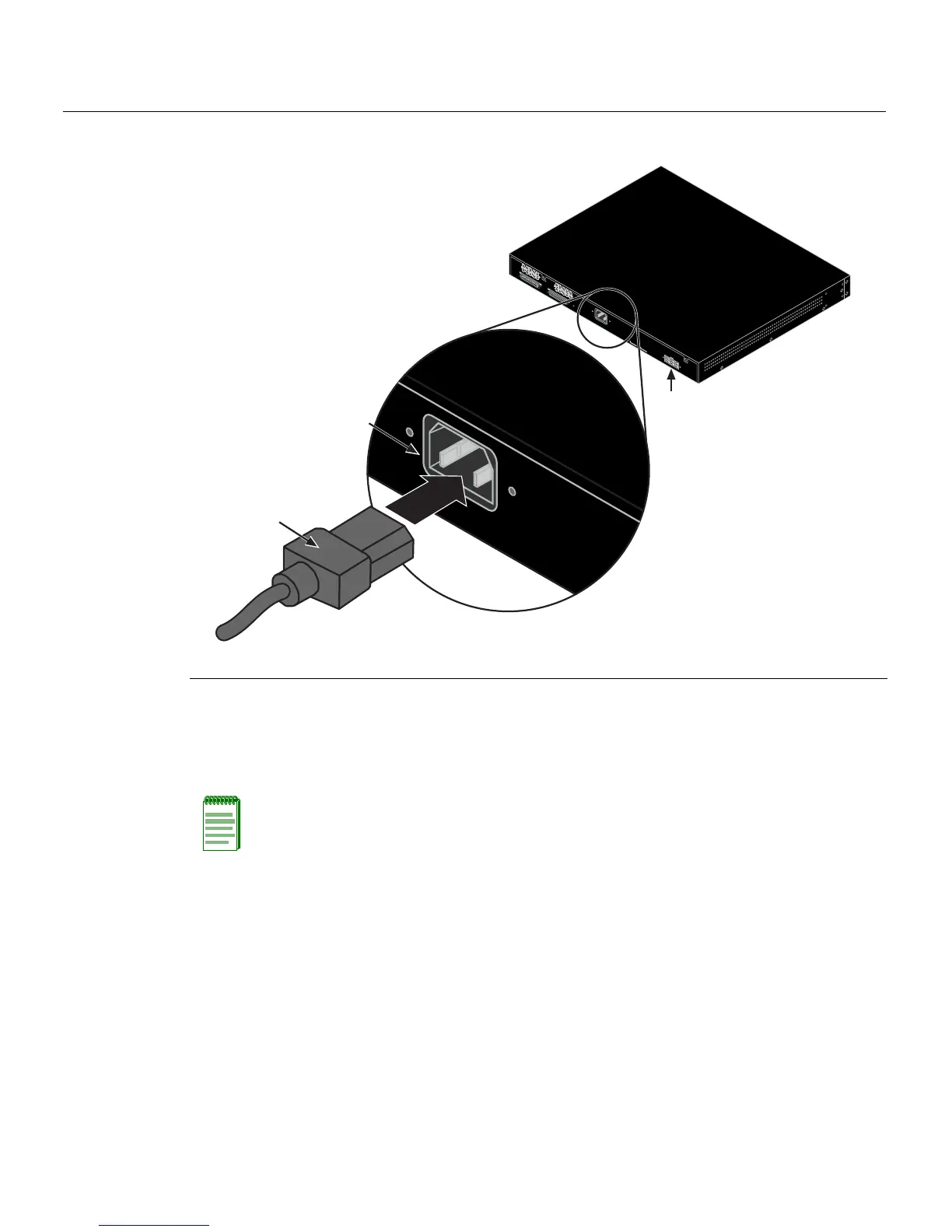
Figure 3-8 Switch Rear View
3. ObservethatthepowerCPULED(notshown),locatedonthefrontpanel.Duringthe
initialization,theCPULEDwillstartbyilluminatingsolidamber,thenstartblinking
green,thenblinkingamber,thenblinkinggreenagainunt iltheendofthe
initialization,andthenturnssolidgreen.
Iftheswitch
isastandaloneswitch,itwilltakeapproximately30 secondsforthe
switchtostartup.Iftheswit chisastackManager,itcantakeupto3minutesormore
tostartup,dependingonthenumberofMemberswitchesinthestack.
1 AC power cord 2 AC power connector 3 Connector for external redundant power supply
Note: If the CPU LED illuminates solid red, there was a critical failure. For more
information about the LED indications and troubleshooting, refer to Chapter 4. If you need
additional help, contact Enterasys Networks. Refer to “Getting Help” on page 1-7 for
details
.
R
e
d
u
n
d
a
n
t
P
o
w
e
r
S
u
p
p
ly
A
C
L
I
N
E
1
0
0
-
2
4
0
V
A
C
5
0
-
6
0
H
z
0
.
8
A
M
A
X
M
A
C
A
D
DR
E
SS
SE
RIA
L
NO
.
S
T
A
C
K
U
P
S
T
A
C
K
D
O
W
N
AC LINE
100-240 VAC
50-60 Hz
0.8 A MAX
À
Á
Â