Installing Optional Mini-GBICs
SecureStack C2 Installation Guide 3-5
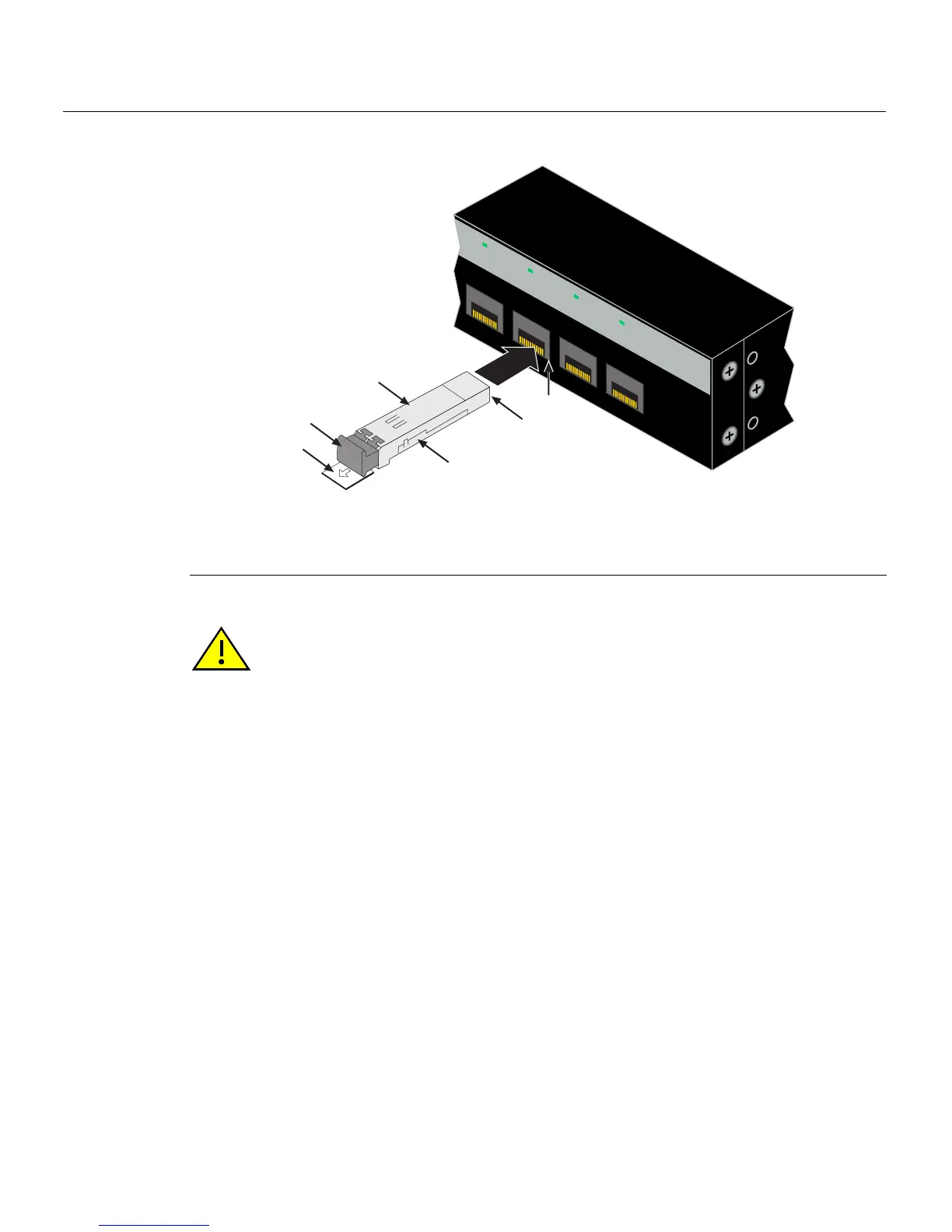
Figure 3-2 Mini-GBIC with LC Connector
Removing the Mini-GBIC
1 Mini-GBIC (MGBIC-LC01 or MGBIC-LC09) 4 Port slot
2 Mini-GBIC
, top side 5 Protective dust cover
3 7-pin edge connector (insertion side) 6 Release tab
Caution: Do NOT remove a Mini-GBIC from a slot without releasing the locking tab
located under the front bottom end of the Mini-GBIC. This can damage the Mini-GBIC.
This is also true of the RJ45 Mini-GBICs with a wire handle. The handle must be pulled
down toward the bottom of the Mini-GBIC to release it.
The Mini-GBIC and its host switch are sensitive to static discharges. Use an antistatic wrist
strap and observe all static precautions during this procedure. Failure to do so could result
in damaging the Mini-GBIC or host switch. Always leave the Mini-GBIC in the antistatic
bag or an equivalent antistatic container when not installed.
Precaución: NO quite el Mini- GBIC de la ranura sin antes abrir la traba ubicada en la
parte frontal del Mini- GBIC. Si lo hace, puede dañar el Mini- GBIC, puesto que es muy
sensible a las descargas de electricidad estática, al igual que el dispositivo host. Utilice la
pulsera antiestática y tome todas las precauciones necesarias durante este
procedimiento. Si no lo hace, pude dañar el Mini- GBIC o el dispositivo host. Mientras no
esté instalado, mantenga el Mini- GBIC en su bolsa antiestática o en cualquier otro
recipiente antiestático.
21
22
23
24
21
22
23
24
C2G124-24
Å
Ä
Á
À
Â
Ã