64
5.2.17. Analog Output Settings
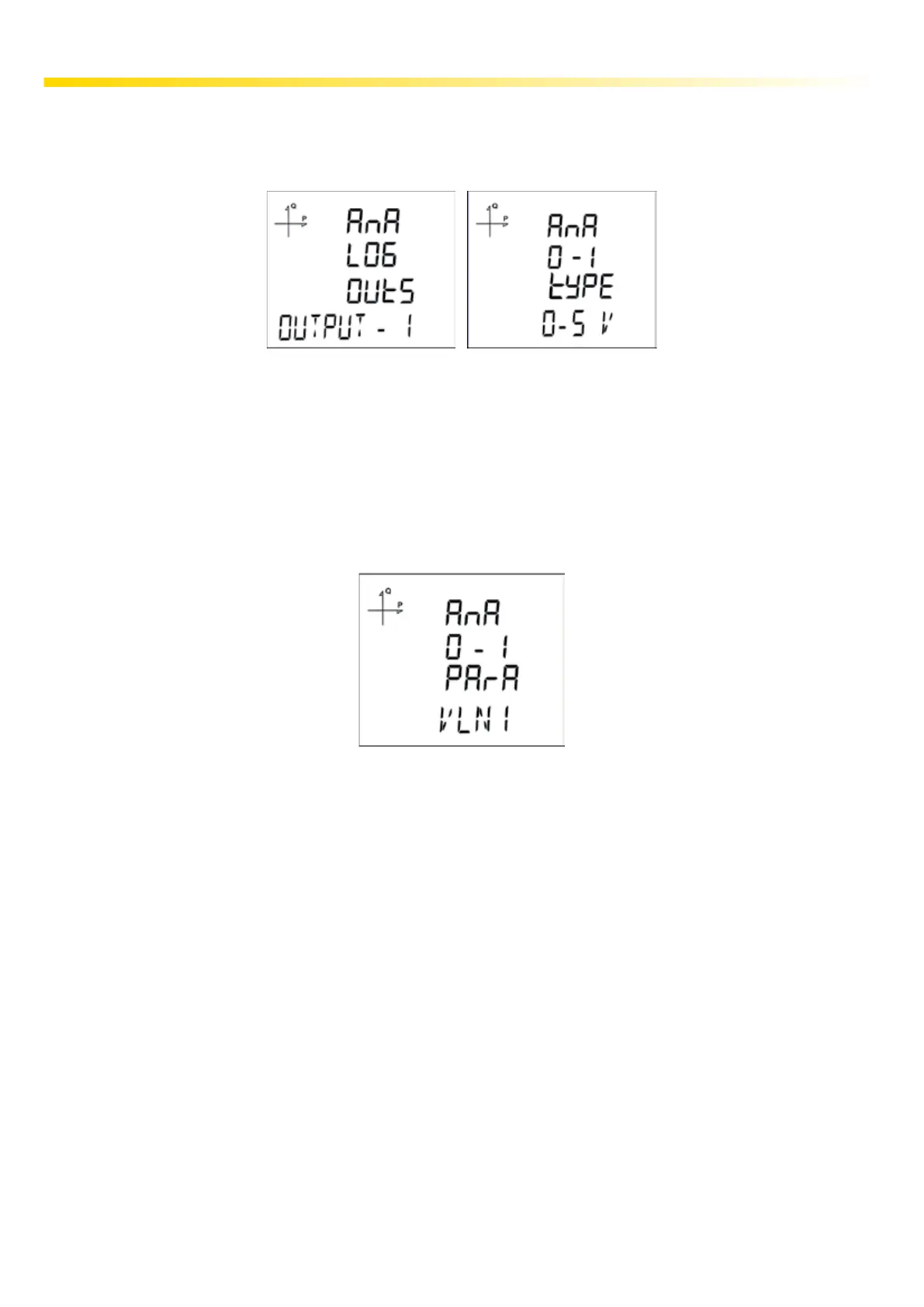
When an analog output module is connected to the device, the purpose of the output is selected from
this menu.
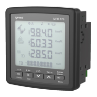
5.2.17.1. Analog Output-1 Type Settings
1. Press the SET button while Analog O-1 Type is displayed.
2. The selected option starts to blink.
3. Select one of 0-5V, 0-10V, -5 ~ 5V and -10 ~ 10V 0-20mA, 0-24mA ve 4-20mA options with
UP/DOWN buttons.
4. After completing your selection, press the SET button.
5. When exiting from the menu with the BACK or ESC button, don’t forget to save the changes.
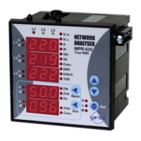
5.2.17.2. Analog Output-1 Parameter Settings
While there is Analog O-1 Parameter on the screen, press the SET button.
1. The selected option starts to blink.
2. Select one of the following options with the Up/Down buttons.
3. After completing your selection, press the SET button.
4. Do not forget to save the changes, when you exit from the menu with BACK or ESC button.
a. VLN1,
b. VLN2,
c. VLN3,
d. VLN4,
e. VLL1,
f. VLL2,
g. VLL3,
h. IL1,
i. IL2,
j. IL3,
k. IL4,
l. IN,
m. IL1 DEMAND
n. IL2 DEMAND,
o. IL3 DEMAND,
p. IL4 DEMAND,
q. IN DEMAND,
r. P1,
s. P2,
t. P3,
u. Q1,
v. Q2,
w. Q3,
x. S1,
y. S2,
z. S3,
aa. Total P,
ab. Total Q,
ac. Total S,
ad. Cos Phi-1,
ae. Cos Phi-2,
af. Cos Phi-3,
ag. Total Cos Phi,
ah. Frekans,
ai. VLN4,
aj. IL4,
ak. Total I,
al. Total I Demand,
am. Total P Demand,
an. Total S Demand,
ao. Total VLN,
ap. Total VLL.