EPSON FX-890/2190 Revision B
Disassembly and Assembly Printer Mechanism Disassembly 82
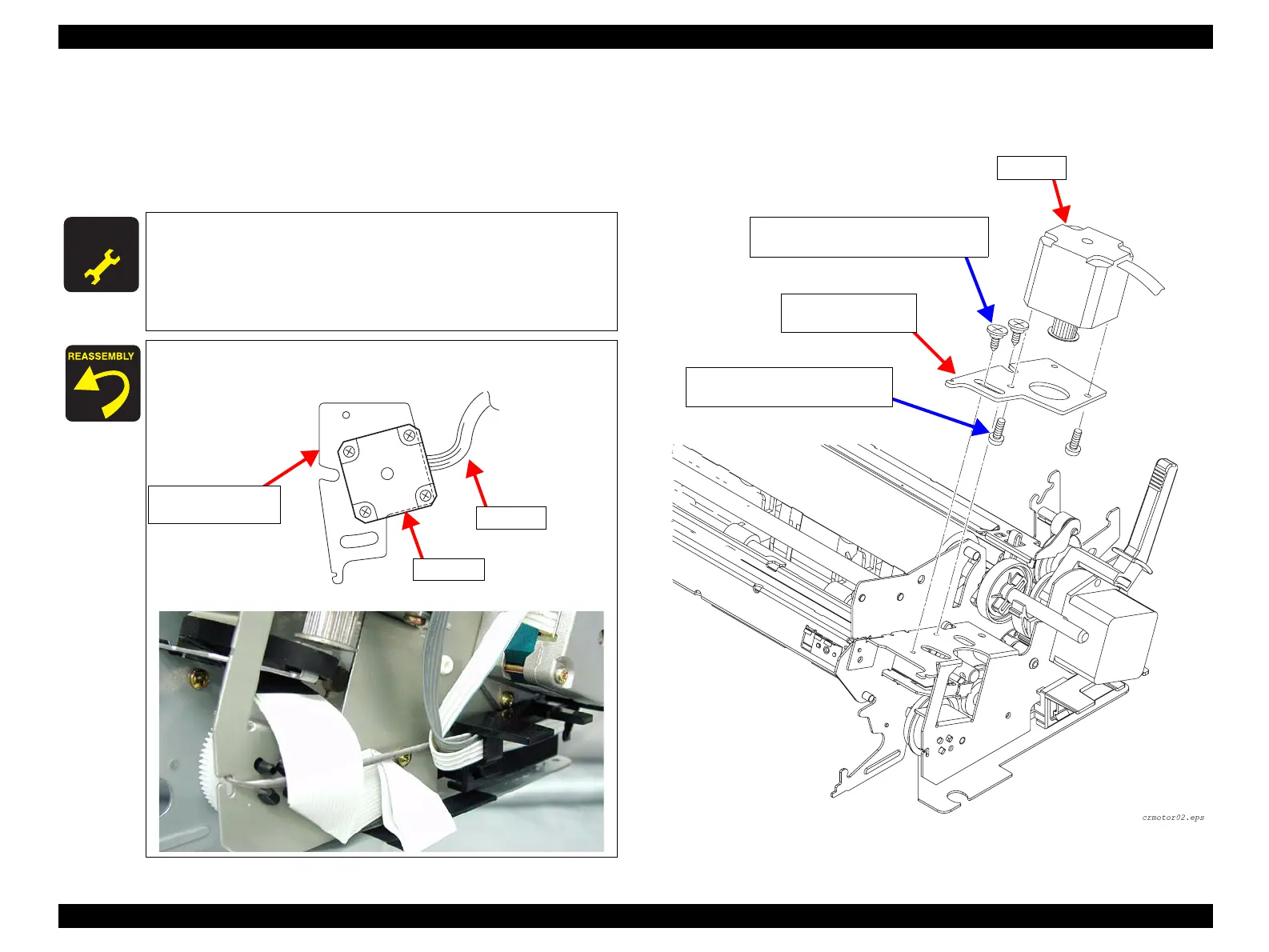
4. Remove the 2 SHAFT,MOUNT,CR (M3x12) screws securing the CR Motor
assembly to the FRAME,SUB,RIGHT, and remove the CR Motor.
(See Figure 4-18)
5. Remove the 2 CB (M3x6) screws securing the CR Motor to the MOUNTING
PLATE,MOTOR,CR, and remove the CR Motor.
Figure 4-18. CR Motor Removal 2
A D J U S T M E N T
R E Q U I R E D
After installing the CR Motor, make the following adjustment:
• Bi-d Adjustment (p.101)
After installing the TIMING BELT,CR, make the following
adjustment:
• Bi-d Adjustment (p.101)
Position the CR Motor assembly on the MOUNTING
PLATE,MOTOR,CR correctly as shown below;
Lead the FFC and lead wires as shown below:
CR Motor
MOUNTING PLATE,
MOTOR,CR
Cable
SHAFT,MOUNT,CR Screws (3x10) x2
Tightening Torque: 0.9±0.1N.m
CB Screws (3x6) x2
Tightening Torque: 0.9±0.1N.m
CR Motor
MOUNTING
PLATE,MOTOR, CR
 Loading...