EPSON FX-890/2190 Revision B
Disassembly and Assembly Printer Mechanism Disassembly 89
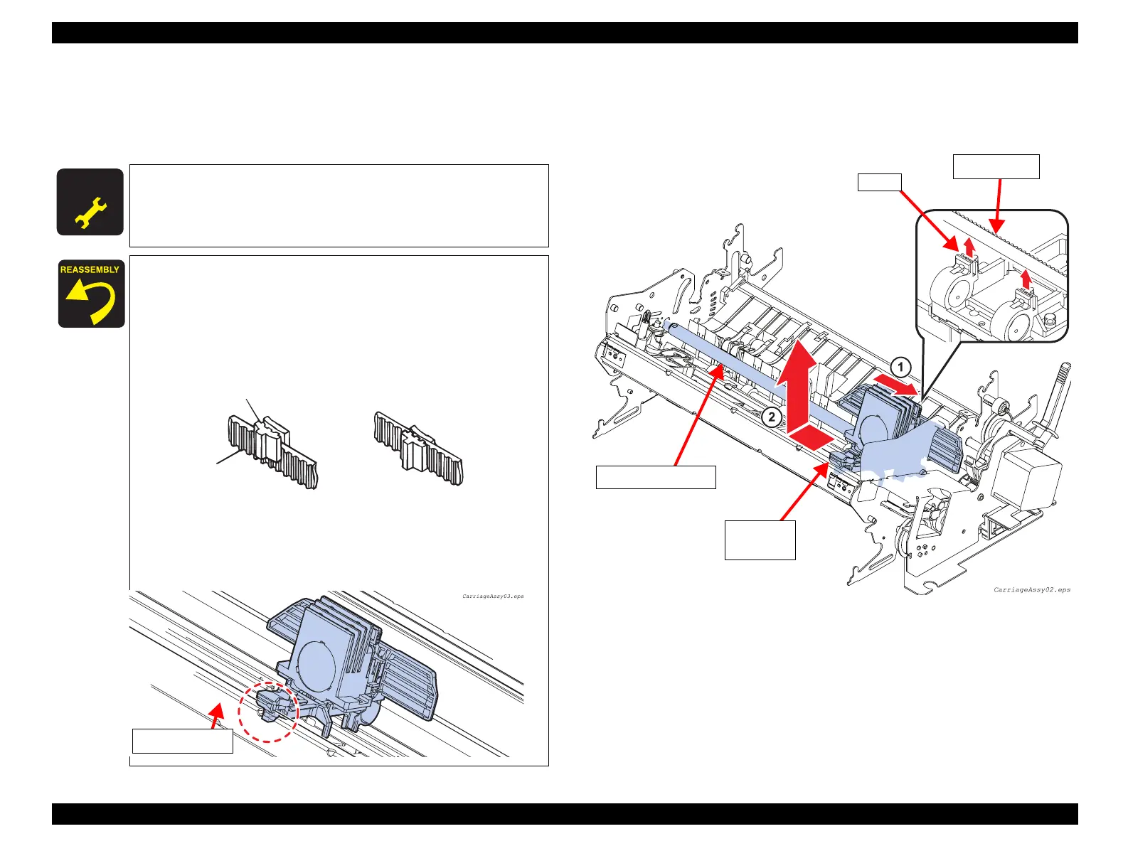
7. Move the Carriage Assembly to the right end, and remove it from the rack of the
FRAME,FRONT with the SHAFT,CR,GUIDE. (See Figure 4-27)
8. Release the TIMING BELT from the 2 clips at the bottom of the Carriage
Assembly.
Figure 4-27. Carriage Assembly Removal 2
A D J U S T M E N T
R E Q U I R E D
After installing the Carriage Assembly, make the following
adjustments:
• Bi-d Adjustment (p.101)
• Platen Gap Adjustment (p.95)
Lubrication is necessary at three points.
(For details, refer to “Lubrication” (p.100) in Chapter 6.)
When attaching the TIMING BELT to the Carriage Assembly,
secure the TIMING BELT with the left and right clips in the
Carriage Assembly, as shown below, and ensure there is no
slack in the TIMING BELT.
Make sure that the groove for the rail in the front of the
Carriage Assembly is fitted on the rail of the FRAME, FRONT.
Clip
<NG>
<OK>
IMING BELT
Frame, FRONT
Carriage
Assembly
SHAFT, CR, GUIDE
TIMING BELT
Clips
 Loading...