3 - 4
Chapter 3 Removal and Replacement Procedures
Epson AcuLaser C2900N
Revision B
Confidential
1.2 General notes
- The string “(PL X.Y.Z)” suffixed to the part name in the procedure denotes that the part corresponds
to the plate (PL) “X.Y”, item “Z” of [Engineering Parts list], and its shape and fitting position can be
checked in [Engineering Parts list].
- Directional descriptions used in the procedures are defined as follows:
-Front : Direction toward you when facing the front of the printer.
-Rear : Direction opposite to the front when facing the front of the printer.
-Left : Left-hand direction when facing the front of the printer.
-Right : Right-hand direction when facing the front of the printer.
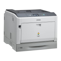
Figure: Definitions of Printer Orientation
- The string “(RRP X.Y)” that appears in or at the end of the procedure denotes that the related service
procedure is described in [RRP X.Y].
- Screws shown in the illustrations are to be unscrewed and removed using a Phillips head (cross-slot)
screwdriver, unless otherwise specified.
- Black arrows shown in the illustrations denote moving directions. When numbers are assigned to
these arrows, they refer to the order in the procedure.
- Refer to [Chapter 4 Plug/Jack (P/J) Connector Locations] for the positions of connectors (P/J).

 Loading...


