Epson Artisan 800/Epson Stylus Photo PX800FW/TX800FW/Epson Artisan 700/Epson Stylus Photo PX700W/TX700W Revision C
DISASSEMBLY/ASSEMBLY Disassembly Procedures 127
Confidential
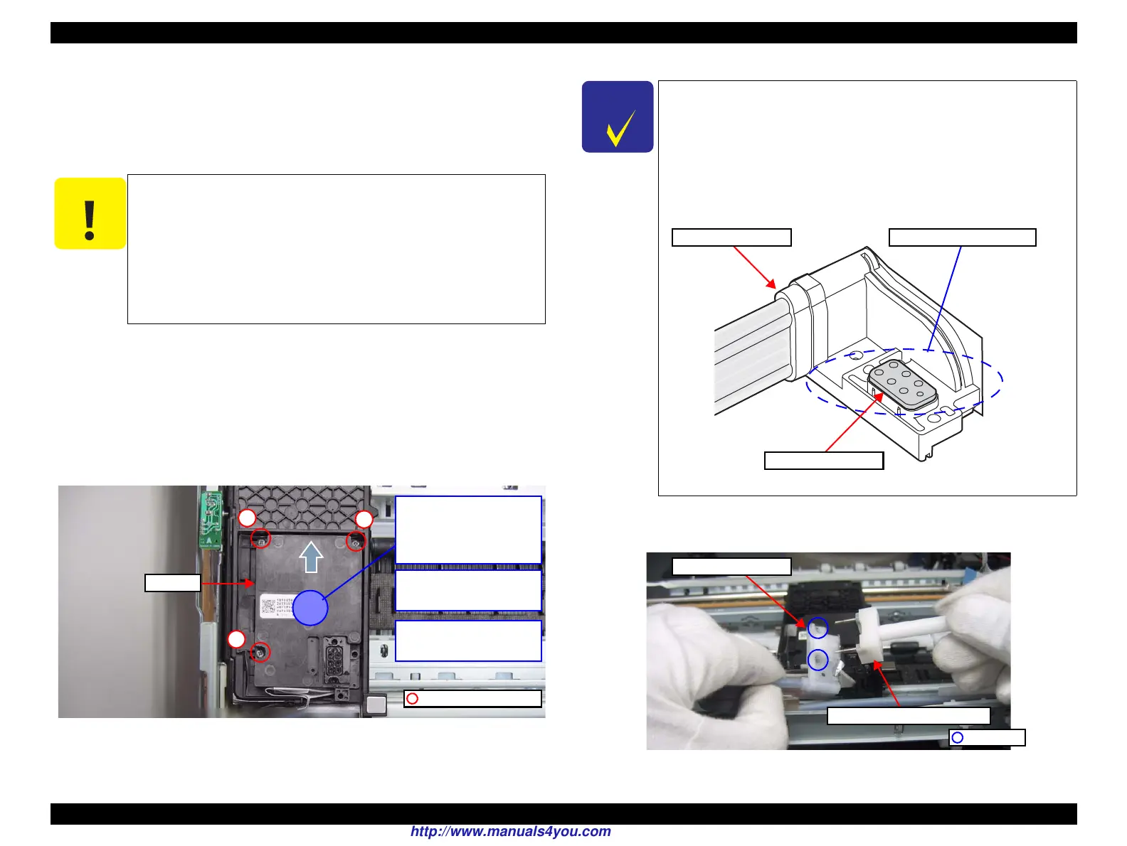
1. Make sure of the installing condition and correct it if there is any gap. (See Fig.
4-62.)
2. Install the Head FFC to the Printhead. (See 4.2.4.1 Printhead Step5 (p125).)
3. Install the Printhead to the Carriage Unit, and secure it as follows:
3-1. Place the hand on the center of the Printhead, and align the screws (x3)
with the screw holes to temporary tighten the screws 1 and 2 alternately
by 90 degrees slowly while pressing the Printhead in the direction of the
arrow shown in
Fig. 4-63.
3-2. Tighten the screw 3 to the same level as the screws 1 and 2 before
completely tighten them.
3-3. Tighten the screws slowly by 90 degrees in the order shown in Fig. 4-63
to secure the Printhead.
Figure 4-63. Assembling the Printhead (1)
4. Insert the tip of the Ink Supply Tube screwing tool to the screw hole of the Ink
Supply Tube Assy.
Figure 4-65. Assembling the Printhead (2)
When tightening the screws that secure the Printhead; to avoid
burring the slot, first align the screw to the hole, and turn it to
the left slightly to engage the threaded parts of the screw and
the hole correctly, then tighten it.
Make sure to follow the specified tightening torque.
When securing the Printhead, make sure to observe strictly the
following. Otherwise, the Printhead may be secured at an
angle, which may adversely affect the print quality.
C.B.P. 2x10 (2.5Kgfcm)
Printhead
1
2
3
2) Tighten the screw 3 to the
same level as the screws 1
and 2.
1) Place the hand lightly on
this point to press the
Printhead, and temporary
tighten the screws 1 and 2
alternately by 90 degrees.
3) Tighten the screws slowly
by 90 degrees in the order
to secure the Printhead.
Make sure to install the Ink Supply Tube Assy after confirming that
the SEAL JOINT,H;B is surely attached on the joint point of the Ink
Supply Tube Assy to the Printhead.
The SEAL JOINT,H;B is not included in the new Ink Supply Holder
IC Assy, therefore, take out the SEAL JOINT,H;B from the old one
in advance, and attach it to the new one without any gap confirming
the correct direction to avoid installing it to the wrong holes.
Figure 4-64. SEAL JOINT,H;B
Joint point to the PrintheadInk Supply Tube Assy
SEAL JOINT,H;B
Ink Supply Tube screwing tool
Ink Supply Tube Assy
Screw hole
http://www.manuals4you.com

 Loading...


