II CORE BLOCK: CLG (Clock Generator)
S1C33L03 FUNCTION PART EPSON B-II-6-1
A-1
B-II
CLG
II-6 CLG (Clock Generator)
This section describes the method for controlling the system clock.
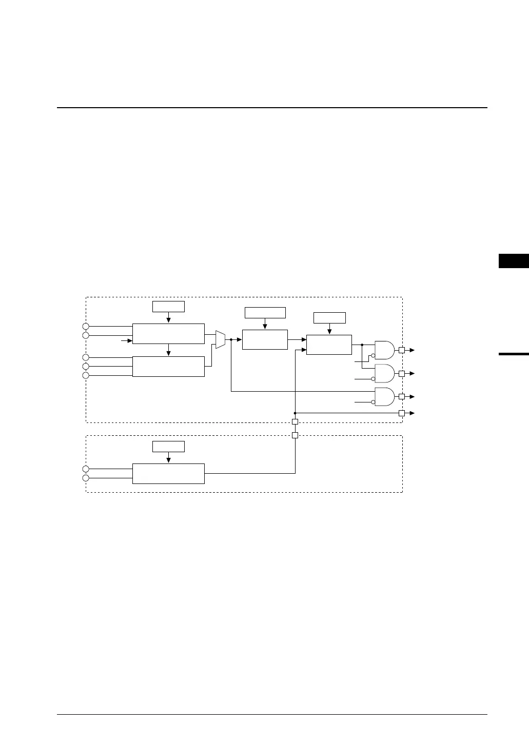
Configuration of Clock Generator
The C33 Core Block has a built-in clock generator that consists of a high-speed oscillation circuit (OSC3) and a
PLL.
The high-speed (OSC3) oscillation circuit generates the main clock for the CPU and internal peripheral circuits
(e.g., DMA, serial interface, programmable timer, and A/D converter).
Furthermore, the clock generator can input a sub clock, such as low-speed (OSC1, 32.768 kHz, Typ.) clock
generated by the Peripheral Block, for the clock timer and for operating the CPU at a low clock speed in order to
reduce current consumption.
Note: When the Peripheral Block including the low-speed (OSC1) oscillation circuit is used, the source
clocks for the CPU and the peripheral circuits (e.g., serial interface, programmable timer, and A/D
converter) can be selected between the OSC3 clock and the OSC1 clock. For details, refer to
"Setting and Switching Over the CPU Operating Clock" in this section and "Prescaler" and "Low-
Speed (OSC1) Oscillation Circuit" of the Peripheral Block.
Figure 6.1 shows the configuration of the clock generator.
High-speed (OSC3)
oscillation circuit
Clock
switch
CLKCHG
To CPU
SLEEP
OSC3
OSC4
HALT, HALT2,
SLEEP
SOSC3
Oscillation ON/OFF
CLKDT[1:0]
Divider
1/1 to 1/8
To BCU and DMA
HALT2, SLEEP
To peripheral circuits
To peripheral circuits
and clock timer
SLEEP
PLL
PLLC
PLLS0
PLLS1
Low-speed (OSC1)
oscillation circuit
SOSC1
Oscillation ON/OFF
OSC1
OSC2
CLG
Peripheral Block
Figure 6.1 Configuration of Clock Generator
After an initial reset, the output (OSC3 clock) of the high-speed (OSC3) oscillation circuit is set for the CPU
operating clock.
When the low-speed (OSC1) oscillation circuit is used, the CPU operating clock can be switched to the output
(OSC1 clock) of the low-speed (OSC1) oscillation circuit in a program. Furthermore, each oscillation circuit can be
stopped in a program.
If the OSC3 clock is unnecessary such as when performing clock processing only, set the OSC1 clock for operation
of the CPU and turn off the high-speed (OSC3) oscillation circuit in order to reduce current consumption. In
addition, when SLEEP mode is set, the high-speed (OSC3) oscillation circuit is turned off, greatly reducing current
consumption (no internal units except for the clock timer need to be operated).
 Loading...