REV.-A
Feedback Circuit
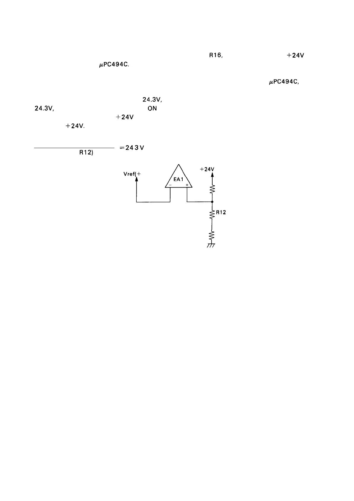
A voltage switching circuit is formed by RI 1, R 12, and
R16,
and the potential of the
+24V
output
voltage is fed back to
PPC494C.
The line between R 12 and R 16 feeds back to the positive terminal of EA 1 in the
PPC494C,
where it
is compared against the standard + 5V voltage. The electric potential of the feedback line becomes
the same as the standard potential at
24.3V,
as shown by the equation below. If the voltage exceeds
24.3V,
the EA1 output goes HIGH, the
(3N
time of the switching pulse drops, the switching duty is
lowered, and, as a result, the
+24V
potential drops. This action is repeated in order to maintain a stable
voltage of
+24V.
5V X (Rl 1+R12+R16)
=
24
a
v
(RI 1 +
R12)
+24V
line
Vref(+
5V)
RI 6
1 9.6K
R12
4.75 K
i
RI 1
316
Figure 2-17. Voltage Feedback Circuit
2-15

 Loading...


