Maintenance 5. Arm #1
G6 Rev.21 127
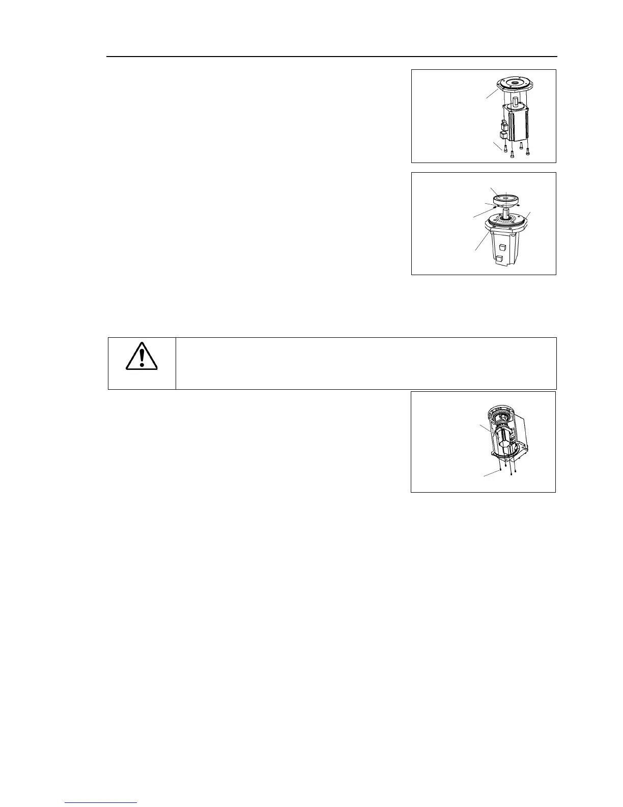
Joint #1 motor
Installation
Mount the motor flange on the Joint #1
Mount the waveform generator on the Joint
without touching the motor axis.
Be sure to fit the end face of the waveform
generator to the end face of the motor
of the motor shaft until the screw
Insert a bushing into the other
screw hole to prevent damage to the motor
See the figures above for the orientation of the waveform generator.
install the waveform generator properly.
Improper installation of the waveform
generator will result in improper function of the Manipulator.
Insert the oil seal and mount the Joint #1
If it is difficult to mount the motor, push it
while moving Arm #1 slowly by hand.
.
Connectors X111, X10, XB10
plate.
For the details, refer to Maintenance: 4.1 Replacing Cable Unit -
Installation Step (6)-2 for Table mounting, Ceiling mounting.
Mount the connector plate.
For details, refer to Maintenance: 3.4 Connector Plate.
maintenance plate.
For details, refer to Maintenance: 3.7 Maintenance Plate.
Perform the calibration of Joint #1.
For details refer to Maintenance: 13. Calibration.