Setup & Operation 5. Motion Range
70 G6 Rev.21
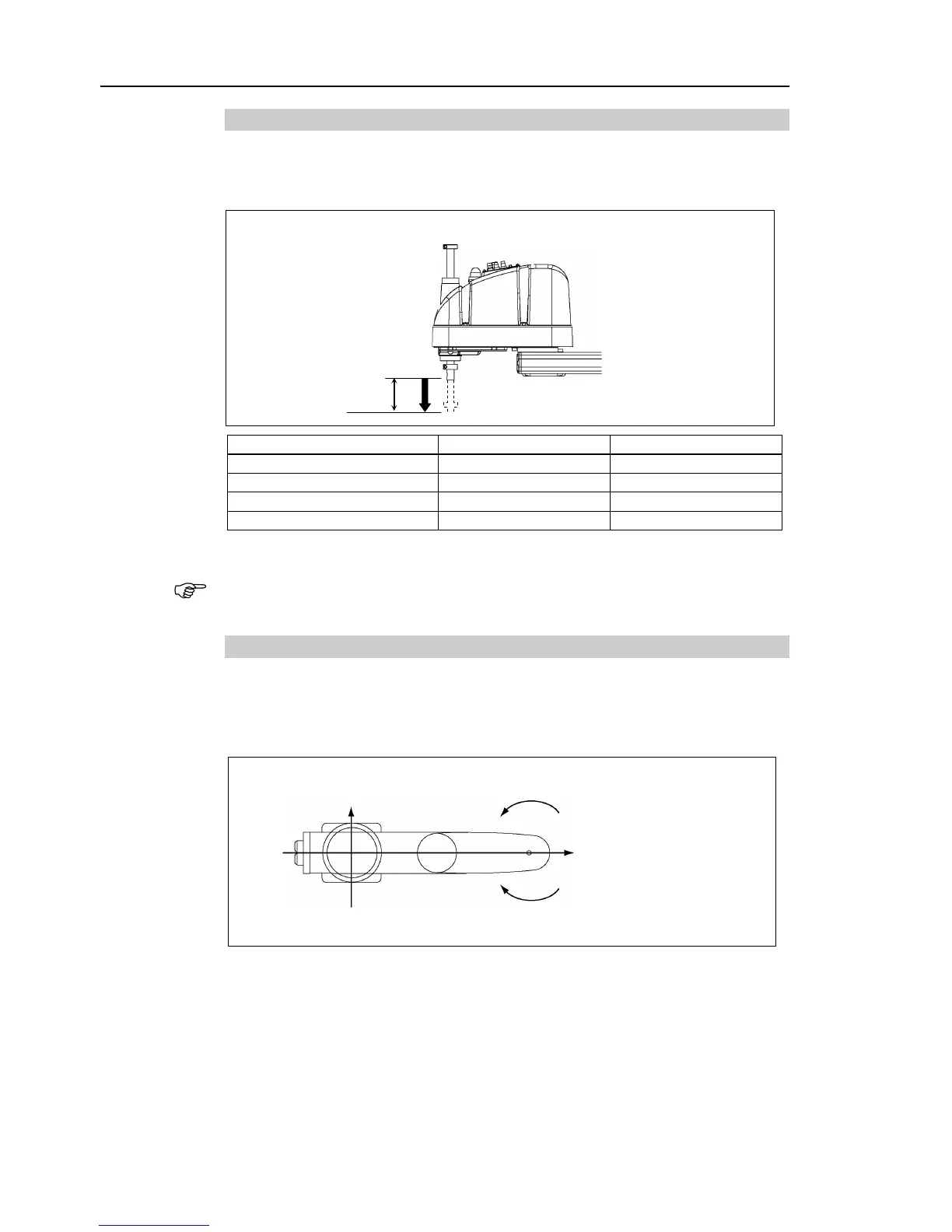
5.1.3 Max. Pulse Range of Joint #3
The 0 (zero) pulse position of Joint #3 is the position where the shaft is at its upper limit.
The pulse value is always negative because Joint #3 always moves lower than the 0 pulse
position.
The bellows for G6-***D* are options at shipment.
For the Cleanroom-model
(G6-***C*) and Protected-model (G6-*** P*/D* with bellows
option)
, the motion range set with the Joint #3 mechanical stop cannot be changed.
5.1.4 Max. Pulse Range of Joint #4
The 0 (zero) pulse position of Joint #4 is the position where the flat near the end of the
shaft faces toward the end of Arm #2. With the 0 pulse as a starting point, the
counterclockwise pulse value is defined as the positive (+) and the clockwise pulse value
is defined as the negative (-).