Maintenance 5. Arm #1
126 G6 Rev.21
5.1 Replacing Joint #1 Motor
Name Quantity Note
Maintenance
parts
AC Servo Motor (400 W) 1
width across flats: 2.5 mm
For M5 set screw, M3 screw
Remove the connector plate.
For details, refer to Maintenance: 3.4 Connector Plate.
Disconnect the following connectors.
Connectors X111, X10 (Hold the claw to remove.)
Connector XB10
Remove the maintenance plate.
For details, refer to Maintenance: 3.7 Maintenance Plate.
For the details, refer to Maintenance: 4.1 Replacing Cable Unit -
Removal Step (7)-2 for Table mounting, Ceiling mounting.
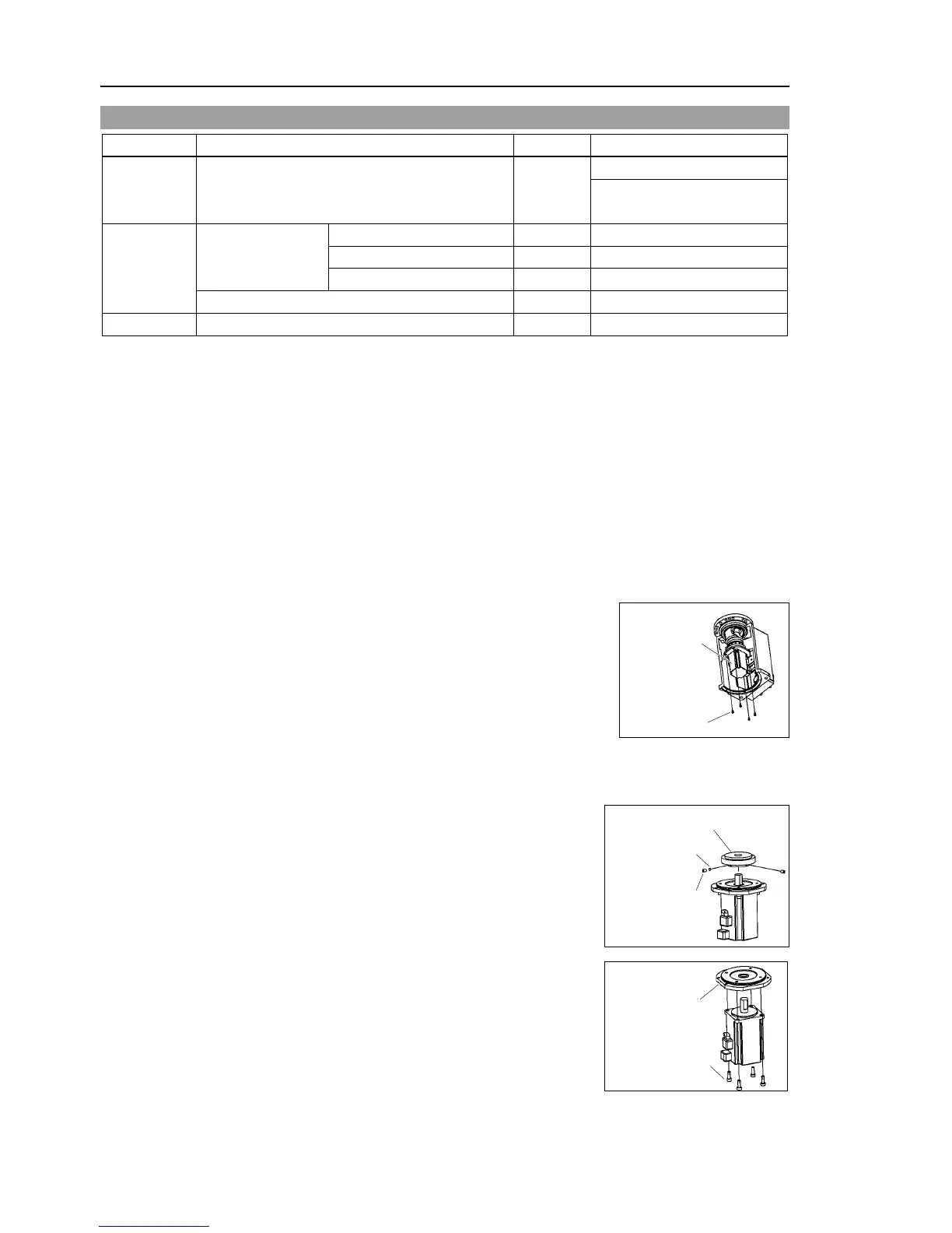
Remove the Joint #1 motor unit from the base.
To do so, unscrew the bolts from the
#1 motor
flange. Then, pull out the motor
To unscrew the two bolts on the
wrench through the maintenance hole.
If the motor cannot be pulled out
pull it out while moving Arm #1 slowly by
hand.
the wave generator from the Joint #1 motor.
There is a brass bushing in one of the
Be careful not to lose it.
flange from the Joint #1 motor.