Setup & Operation 5. Motion Range
G6 Rev.21 75
5.2.2 Setting the Mechanical Stop of Joint #3
This method applies only to the Standard-model Manipulator (G6-***S*)/Protected-model
Manipulator (G6-***D* without bellows option).
For the Cleanroom-model (G6-***C*) and Protected-model (G6-***D* with bellows option),
the motion range set with the Joint #3 mechanical stop cannot be changed.
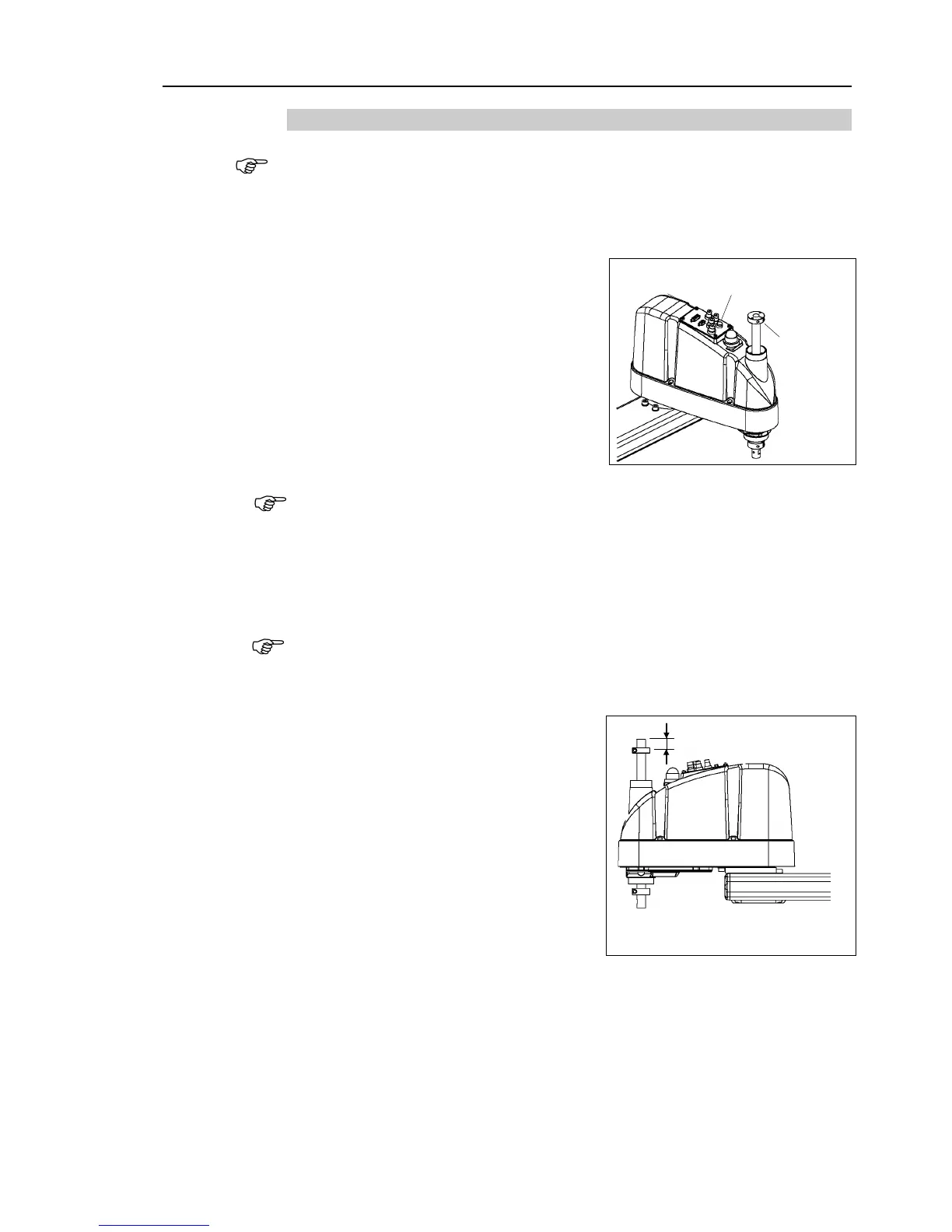
Turn ON the Controller and turn OFF the motors using the Motor OFF
Push up the shaft while pressing the brake
release
Do not push the shaft up to its upper limit
or it will be difficult for the arm top cover
to be removed. Push the shaft up to a
position where the Joint #3 mechanical
stop can be
Lower limit
mechanical
stop
2-M5×6
the brake release switch, the shaft may lower and rotate due to the
weight of the end effector.
Be sure to hold the shaft by hand while pressing the
Loosen the lower limit mechanical stop screw (M4
A mechanical stop is mounted on both the top and bottom of Joint #3. However, only
the position of the lower limit mechanical stop
on the top can be changed.
Do not
remove the upper limit mechanical stop on the bottom because the calibration point of
Joint #3 is specified
The upper end of the shaft
want to limit the stroke.
For example, when the lower limit
mechanical stop is set at “
the lower limit Z coordinate value is
“
-150”. To change the value to “-100”,
move the lower limit mechanical stop
down
“50 mm”. Use calipers to measure
Firmly tighten two lower limit mechanical stop screws (M4
15) so that they do not
enter the shaft groove.
Recommended tightening torque: