Maintenance 7. Arm #3
G6 Rev.21 141
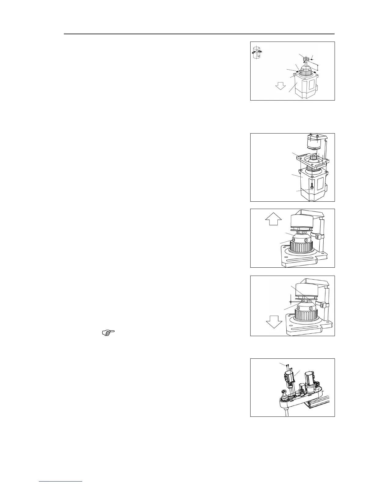
Joint #3 motor
Installation
Secure the pulley to the new motor shaft.
Be sure to fit the end face of the pulley to
screws on the flat face of
the motor shaft until the screw just
bushing into the other set screw hole to
prevent damage to the motor shaft.
Mount the Z plate to the Joint #3 motor.
Screw : 4-M5×12
Tightening torque : 7.0 N⋅m (71.3 kgf⋅cm)
4-M5x12
[Torque:700Ncm
(71.3 kgf⋅cm)]
ush up the pulley to the brake and tighten the
down the hub to the pulley side.
ighten the screws with the space 0.1 - 0.3 mm
If the hub is secured with the space larger than 0.3
mm, the brake hub may interfere with the movable
plate. This may grind the movable plate and cause
metal powder.
Place the Joint #3 motor unit in the arm so
the motor cable faces toward the
Make sure that the rotor hub on the end
the pulley is completely set in the