EasyManuals Logo
Home>Epson>Robotics>SCARA ROBOT

Epson SCARA ROBOT User Manual

Epson SCARA ROBOT
216 pages
To Next Page IconTo Next Page
To Previous Page IconTo Previous Page
Page #160 background imageLoading...
Page #160 background image
Maintenance 7. Arm #3
148 G6 Rev.21
Joint #3 brake
Installation
(1)
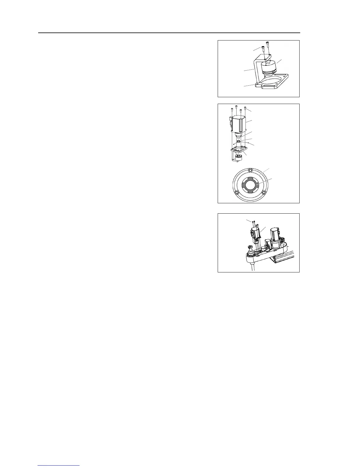
Mount the brake to the brake plate.
2-M3×10
Brake
Z plate
Brake
plate
(2)
Mount the brake hub to the Z1 pulley.
For the brake hub mounting procedure, refer
to
the
section 7.1 Replacing Joint #3 Motor - Joint
#3 motor installation
- Step (1) - (4).
(3) 4-M5×12
Joint #3 motor
Z plate
Z1 pulley
Brake hub
(2) 2-M3×4
set screw
Disk
Hub
(3)
Mount the motor unit to the Z plate.
Align the
position of the disk on the brake and
the hub.
When the brake disk is not aligned, turn ON the
Controller and connect the connector X32.
Press the brake release switch and release the
brake to manually adjust the position.
(4)
Mount the Joint #3
brake unit to Arm #2 so that
the open side faces toward the end of the arm.
4-M4
×12
+ Washer
Joint #3
motor unit
(5)
Connect the connectors
.
Connectors X231, X31, X32, X63
(6)
Re
-bundle the cables in their original positions with a wire tie removed in step (5).
Do not
allow unnecessary strain on the cables.
(7)
Install the arm
top cover and the arm bottom cover.
For details, refer to Maintenance: 3. Covers.
(8)
Perform the calibration of Joint #3.
For details, refer to Maintenance: 13. Calibration.

Table of Contents

Questions and Answers:

Question and Answer IconNeed help?

Do you have a question about the Epson SCARA ROBOT and is the answer not in the manual?

Epson SCARA ROBOT Specifications

General IconGeneral
BrandEpson
ModelSCARA ROBOT
CategoryRobotics
LanguageEnglish

Related product manuals