Maintenance 8. Arm #4
G6 Rev.21 155
Push down the shaft to its lower limit while pressing the brake release switch.
sure to keep enough space and prevent the
end effector hitting any peripheral
The brake release switch is applied to both Joints #3 and #4. When the brake release
switch is pressed, the
respective brakes for Joints #3 and #4 are released
(The brake for Joint #4 is only installed to G6-**3**.)
shaft falling and rotating while the brake release switch is being
because the shaft may be lowered by the weight of an end effector.
top cover and the arm bottom cover.
For details, refer to Maintenance: 3. Covers.
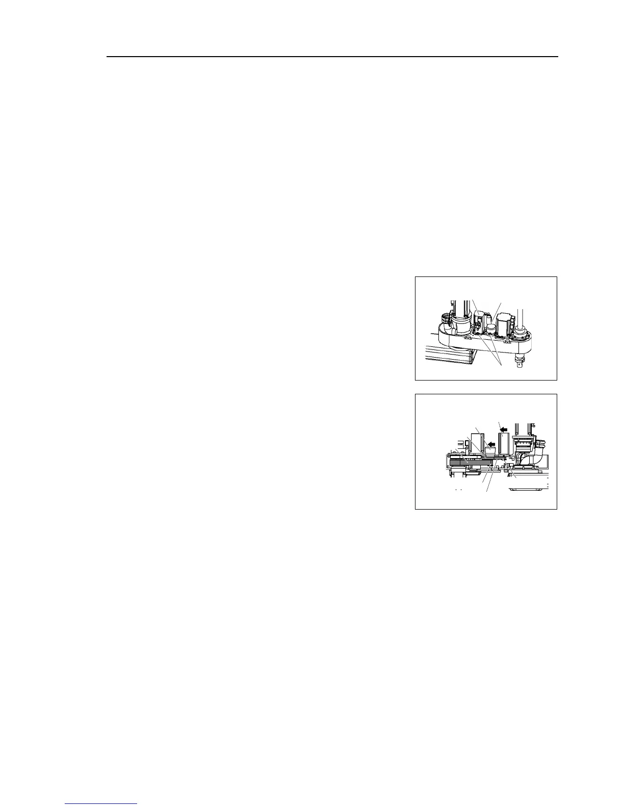
Loosen the bolts securing the Joint #4 motor
unit.
Joint #4
intermediate
shaft unit
Loosen the blots securing the Joint #4
intermediate shaft unit.
Remove the U2 belt from the U2 small pulley
and remove the U1 belt from the U1 pulley and
U2 large pulley.
Joint #4
Intermediate
shaft unit
ut the Joint #4 motor unit and the Joint #4
intermediate shaft unit to the shaft side and
remove the belt from the pulley.